Vacuum deposition device

An evaporation and vacuum technology, which is applied in the directions of vacuum evaporation plating, sputtering plating, ion implantation plating, etc., can solve the problem of weak directivity of evaporated materials and failure of evaporated materials to reach film-forming objects and evaporated materials Problems such as poor adhesion efficiency

Active Publication Date: 2021-06-22
ULVAC INC
View PDF4 Cites 0 Cited by
  • Summary
  • Abstract
  • Description
  • Claims
  • Application Information

AI Technical Summary

Problems solved by technology

[0003] Here, in the above-mentioned vapor deposition source, when the vapor deposition substance is ejected from the nozzle in a vacuum chamber with a vacuum atmosphere, the directivity of the vapor deposition substance is weak, and the vapor deposition substance will appear at a large angle with respect to the hole axis in the vacuum chamber. Scatter within range
Therefore, if a gap is left on the vapor deposition source side of the object to be filmed and a mask material is provided therein, there is a problem that the vapor deposition substance goes around depending on the angle of attachment of the vapor deposition substance when it reaches the object to be filmed. The area that should be masked by the mask material is attached to the object to be film-formed, and a film is formed with an outline larger than the opening of the mask material (so-called mask effect (mask effect)) (usually, when the above-mentioned evaporation source is used from When the vapor deposition material is ejected from each nozzle, among the vapor deposition materials scattered from the nozzle on one side of the Y-axis direction, the deposition angle is when the vapor deposition material adheres to the part of the film-forming object located on the other side of the Y-axis direction minimum)
However, with the vapor deposition source of this conventional example, there is a problem that most of the vapor deposition substances ejected from the nozzles in both peripheral regions cannot reach the film-forming object, and the deposition efficiency of the vapor deposition substances deteriorates.

Method used


Image

  • Vacuum deposition device
  • Vacuum deposition device
  • Vacuum deposition device

Examples


Embodiment Construction

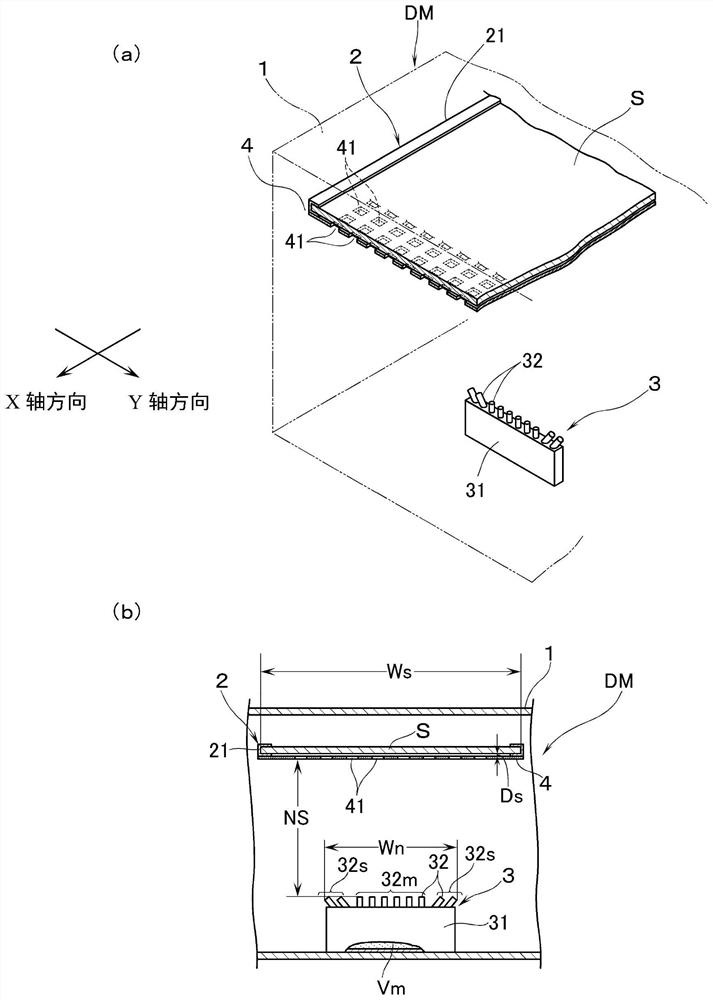
[0021] Referring to the accompanying drawings, a glass substrate with a predetermined thickness having a rectangular outline is used as the object to be filmed (hereinafter referred to as "substrate S"), and a case where a predetermined thin film is formed on one side of the substrate S is taken as an example to illustrate the vacuum evaporation method of the present invention. Embodiment of the plating apparatus. Hereinafter, terms indicating directions such as up and down are figure 1 Describe the basis.

[0022] refer to figure 1 (a) and (b), the vacuum evaporation device DM has a vacuum chamber 1 . Although not particularly illustrated, a vacuum pump is connected to the vacuum chamber 1 through an exhaust pipe, and it can be evacuated to a predetermined pressure (vacuum degree) and maintained. Furthermore, a substrate transfer device 2 is provided on the upper portion of the vacuum chamber 1 . The substrate conveying device 2 has a conveyer 21 that holds the substrate ...


PUM


Abstract

The present invention provides a vacuum vapor deposition device capable of effectively suppressing the masking effect and forming a film with high adhesion efficiency of vapor deposition substances. It has: an evaporation source (3), which is arranged in a vacuum chamber (1); a moving device, which moves a substrate (S) relative to the evaporation source in one direction; and a mask material (4). The relative movement direction of the substrate relative to the evaporation source is regarded as the X-axis direction, and the width direction of the substrate is regarded as the Y-axis direction. Arrange settings. The intervals between the nozzles located at both ends in the Y-axis direction are narrower than the width (Ws) of the substrate according to the distance (NS) between the nozzles and the object to be filmed. The nozzles located in the central area in the Y-axis direction are used as the main nozzles (32m), and the nozzles located on the outside of each side in the Y-axis direction are used as sub-nozzles (32s). Intersecting hole axes (33), and the nozzle hole of the secondary nozzle has a hole axis (34) inclined to the outside of the Y-axis direction relative to the hole axis of the main nozzle.

Description

technical field [0001] The present invention relates to a vacuum evaporation device, which has an evaporation source arranged in a vacuum chamber, and a moving device for relatively moving an object to be filmed in one direction in the vacuum chamber with respect to the evaporation source. Background technique [0002] Such a vacuum vapor deposition apparatus is known in Patent Document 1, for example. In this device, the direction of relative movement of the vapor deposition source with respect to a rectangular glass substrate or other film-forming object is defined as the X-axis direction, and the width direction of the film-forming object perpendicular to the X-axis direction is defined as the Y-axis direction. The evaporation source has a storage box for accommodating the evaporation material, and on the surface of the storage box opposite to the object to be filmed, nozzles (cylindrical nozzles) of the evaporated material are arranged at regular intervals in the Y-axis ...

Claims


Application Information

Patent Timeline
Patent Type & Authority Patents(China)
IPC IPC(8): C23C14/24C23C14/04
CPCC23C14/04C23C14/24C23C14/042C23C14/225C23C14/243
Inventor 北泽僚也汲田健太郎菊地诚
Owner ULVAC INC
Why Eureka
Try Eureka