
Connecting element

A technology for connecting splints and splints, used in elevators, transportation and packaging, etc., can solve the problems of small wall thickness, high cost, impossible to achieve, etc., and achieve the effects of good strength, low cost, and easy manufacturing.

Active Publication Date: 2011-06-15
INVENTIO AG
View PDF1 Cites 0 Cited by
  • Summary
  • Abstract
  • Description
  • Claims
  • Application Information

AI Technical Summary

Problems solved by technology

Furthermore, according to this embodiment, it is necessary to carry out mechanical or cutting work on the surface abutting against the guide rail
The strength can be improved by the Y shape, on the other hand, the connecting splint made by casting is heavy and it is almost impossible to achieve a small wall thickness due to the processing technology, so it takes up a lot of space
[0007] It is also possible to manufacture the connecting splints by welding, but this is also expensive and must be followed by straightening and / or heat treatment
[0008] The main disadvantages of the connection splints known hitherto are the high cost and the large space required

Method used


Image

  • Connecting element
  • Connecting element
  • Connecting element

Examples


no. 1 approach

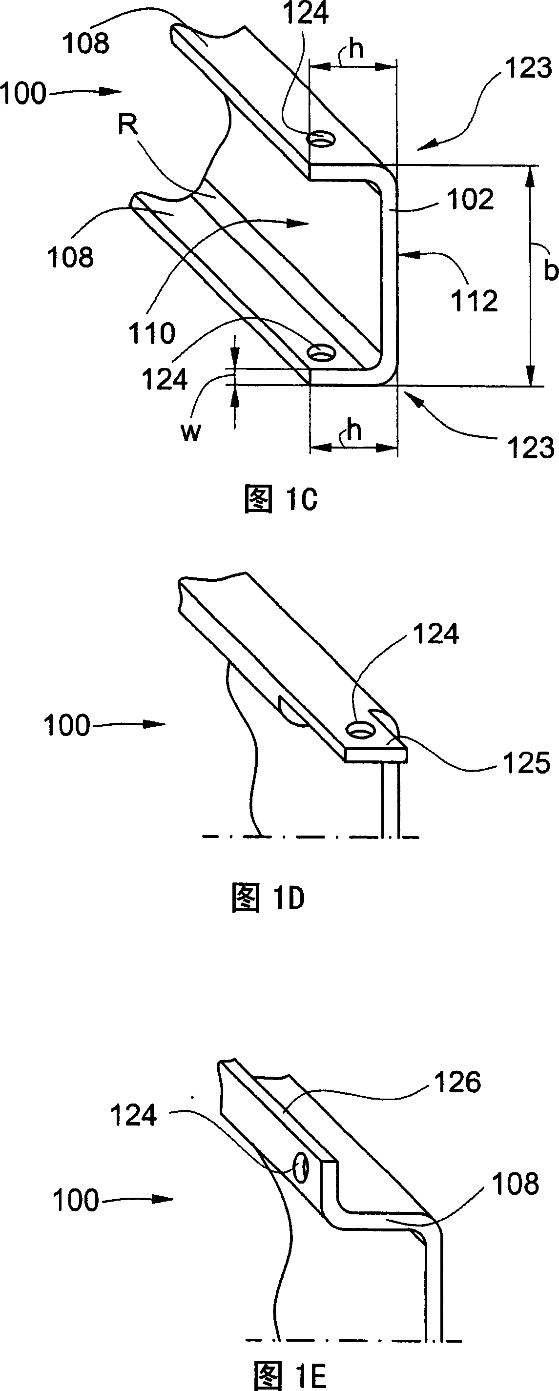
[0059] The flange height h of the two longitudinal flanges 108 can also be different, and said flange height of a longitudinal flange does not have to be constant.

[0060] In FIG. 1C , the difference from FIG. 1A is that the eyelets 124 are provided on the flange 108 . The holes can be utilized when shipping and / or installing the rail.

[0061] Additional embodiments are shown in Figures ID and IE. FIG. 1D shows a connecting lug 100 which has a plate 125 with a hole 124 . FIG. 1E shows a connecting bridge 100 which has a bridge 126 along at least one flange 18 . The bridge 126 can be used as a connection aid. In addition, the bridging elements can increase the rigidity of the connecting splint 100 .

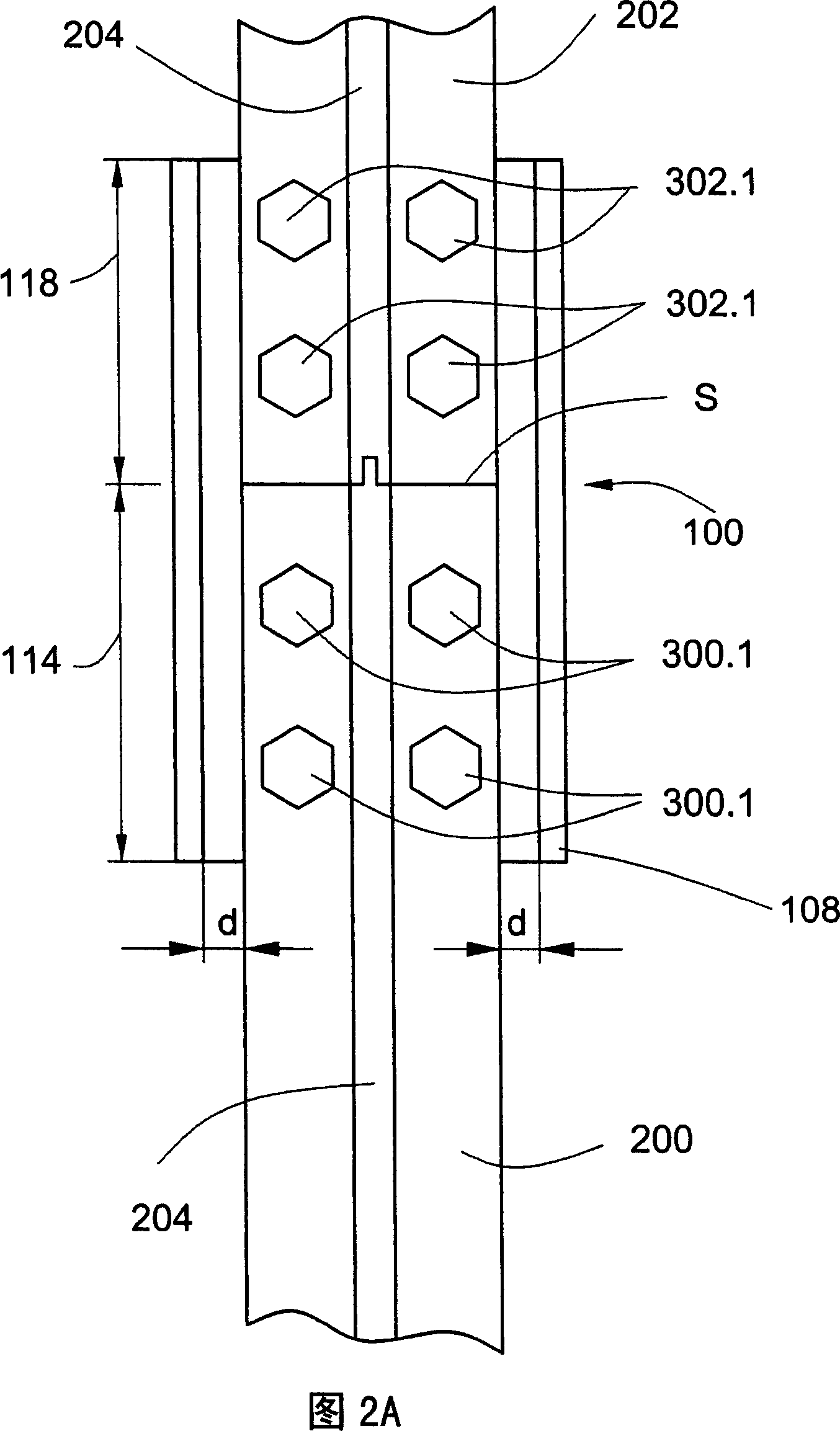
[0062] 2A and 2B show a connecting splint 100 having the structure of the connecting splint 100 shown in FIG. 1 . The connecting splint 100 is used to connect one guide rail part 200 with another guide rail part 202 . The structure of the connection clamp should make its l...


PUM


Abstract

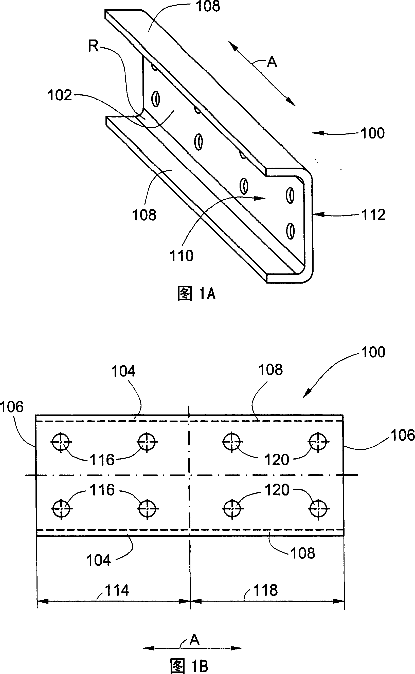
The invention relates to a connecting fishplate (100) for fastnessing a guide rail element (200) and the guide rail element (200) is directional at the transportion direction (A) of an elevator. The connecting fishplate (100) comprises a plate part (102) having longitudinal brims (104) extending along the transportion direction (A). One flat piece (110) of the plate part (102) leans against tips of the guide rail element (200). An auxiliary body is arranged to fix the connecting fishplate (100) to the guide rail element (200), wherein the plate part (102) has longitudinal limbs (108) on its longitudinal brims (104), the longitudinal limbs (108) is vertical to its longitudinal brims (104), so the connecting fishplate (100) has a U-shape section which is vertical to the transportion direction (A). The plate part (102) and its longitudinal limbs (108) is made by bending board, optionaly bending board through die such as armor plate.

Description

technical field [0001] The invention relates to a connecting splint for fixing guide rail components. Background technique [0002] Such connecting cleats, especially when used in elevator installations, are also referred to as connecting fishplates. Elevator installations usually have at least one guide rail which extends in the conveying direction and serves to guide the moving elevator components. Rails are usually made up of several rail pieces. A common connecting splint is used to fix two continuous guide rail parts to each other, ie the connecting splint connects the rail ends of such guide rail parts to each other. [0003] The known connecting bridges consist essentially of a plate part which extends over the ends of two adjacent rail parts and is fastened to these two rail parts. A plate surface of the plate part abuts against the guide rail part. The plate part has two longitudinal edges, which extend in the conveying direction, and two transverse edges, which...

Claims


Application Information

Patent Timeline
Patent Type & Authority Patents(China)
IPC IPC(8): B66B7/02
CPCB66B7/02
Inventor 彼得・默利
Owner INVENTIO AG
Learn More