
Burner for cooking oven

A technology of burners and cooking stoves, which is applied in the direction of burners, gas fuel burners, combustion methods, etc., and can solve problems such as entering the burner head

Inactive Publication Date: 2007-01-17
RINNAI CORP
View PDF0 Cites 5 Cited by
  • Summary
  • Abstract
  • Description
  • Claims
  • Application Information

AI Technical Summary

Problems solved by technology

[0008] However, in the above-mentioned conventional burner, when the boiling soup overflowing from the pot is very intense, in the state where the soup (A) is attached to the top surface of the passage (20) for the flame port, it is easy to quickly burn it. flow to its inner end (200), thus, there is a problem of entering the gas passage (13) of the burner head (1) over the inner circumference (110) of the conical seat surface (11)

Method used


Image

  • Burner for cooking oven
  • Burner for cooking oven
  • Burner for cooking oven

Examples


Embodiment Construction

[0028] Hereinafter, the best mode for carrying out the present invention will be described with reference to the drawings.

[0029] [First implementation form]

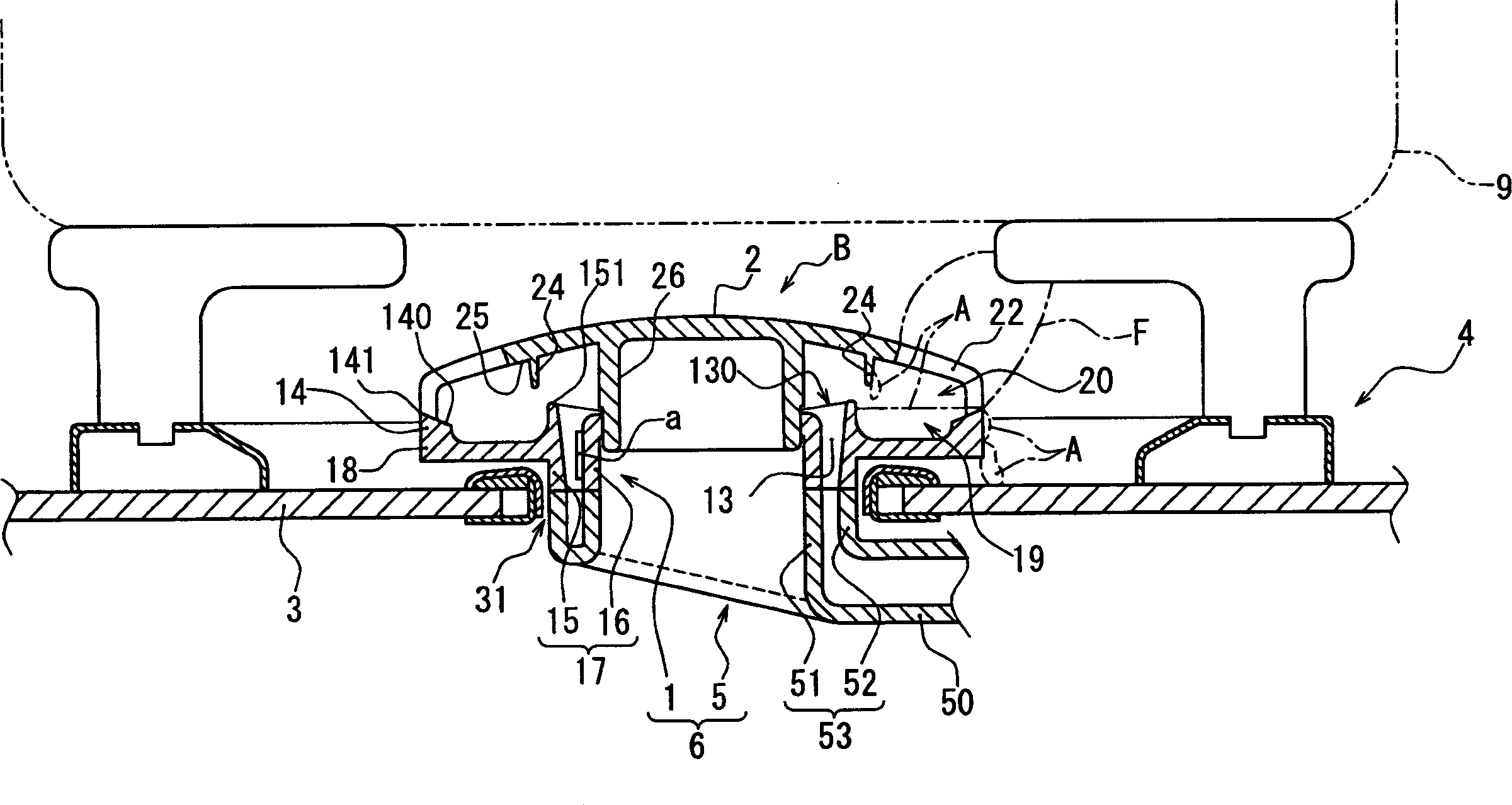
[0030] Such as figure 1 As shown, the burner (B) for a cooking stove according to the first embodiment of the present invention is in the form of protruding upward from the burner opening (31) provided on the cooking stove top plate (3) for a gas cooking stove set up. On the cooking stove top plate (3), a fire support (4) is arranged at a position surrounding the cooking stove burner (B).

[0031] A burner (B) for a cooking stove has a burner body (6) composed of an annular burner head (1) and a mixing tube (5) connected to and arranged below it. At the same time, the burner head (1) On it, a burner cover (2) having the same outer diameter is placed in an overlapping state.

[0032] The structure of the mixing tube (5) is that a double tube part (53) composed of concentric inner and outer tubes (51) (52) is conne...


PUM


Abstract

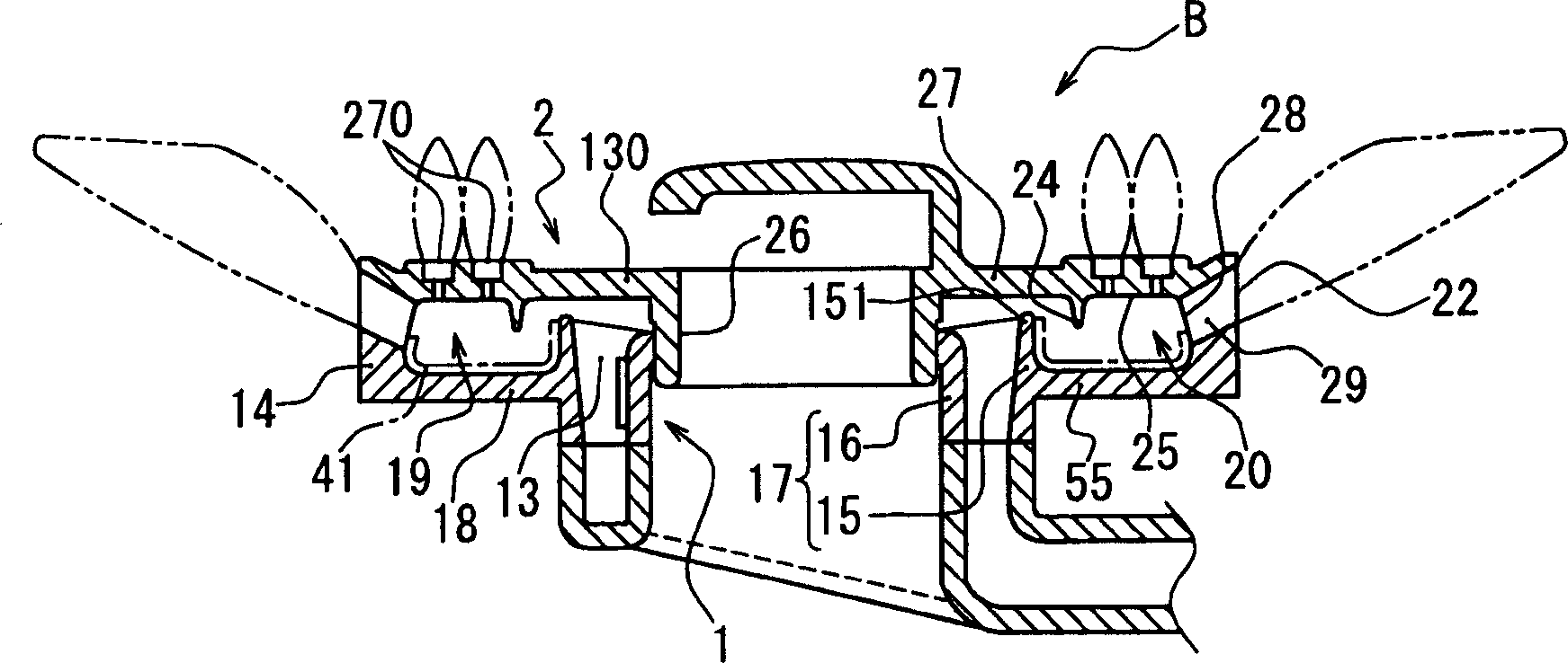
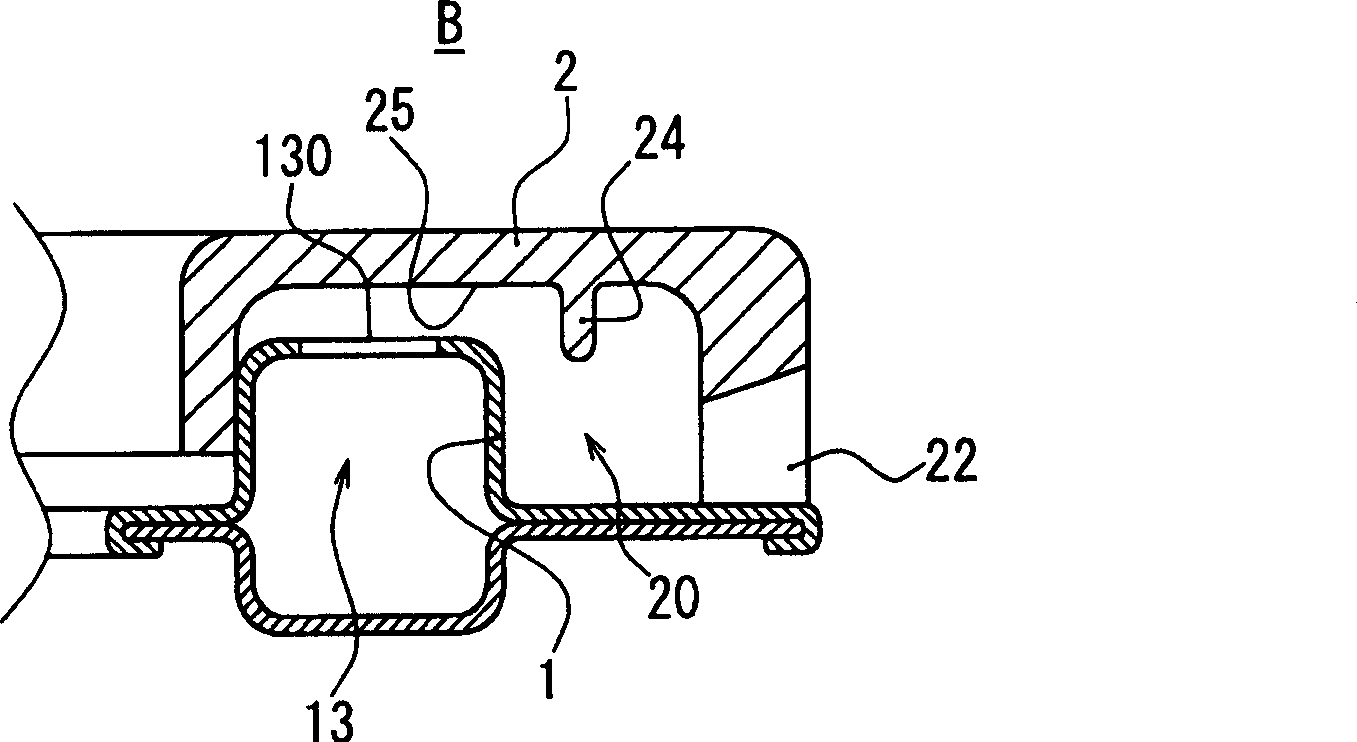
This invention relates to a burner for gas stove of which the burner cap is placed on the circular burner head in an overlapped manner. The burner head is penetrated through the gas passage whose downstream end is open toward the overlapped boundary between the burner head and the burner cap. The burner port passageway of the burner port is formed underneath the burner cap, extending from the burner port toward the center side, and is connected to the opening of the downstream end of the gas passage. The burner port is formed on the outer face of the burner cap. Soup or any liquid is prevent from entering the gas passage of the burner head by means of blocking the soup or liquid to flow into the burner along the ceiling surface of burner port passageway. The opening of the downstream end of the gas passage is formed at a higher location in relation to the lower part of the burner port. A suspended wall is suspended from the ceiling surface of the burner port passageway is mounted on a radial outer side of the opening of the downstream end of the gas passage.

Description

technical field [0001] The present invention relates to a burner for a cooking stove incorporated in a gas stove such as a desktop cooking stove. Background technique [0002] As a burner for cooking stoves in the past, such as Figure 4 As shown, there is a structure in which the burner cover (2) is placed on the annular burner head (1). [0003] The conical seating surface (11) formed on the outer periphery of the upper surface of the annular burner head (1) gradually becomes higher toward the center, and at the same time, the lower part of the burner cover (2) is placed on the conical seating surface (11). An annular wall (21) at the outer periphery of the surface. [0004] The passage (20) for the flame port (20) that rises toward the flame port (22) at the outer end passes through the vicinity of the upper end of the annular wall (21) of the burner cover (2), and at the same time, forms a soup on the lower surface of the annular wall (21). The juice returns to the tan...

Claims


Application Information

Patent Timeline
IPC IPC(8): F24C3/00
CPCF23D14/065F23D14/58F24C3/085F24C15/107F24C15/108
Inventor 猪股匡顺
Owner RINNAI CORP
Learn More