
Method for realizing high-speed following ink-jet printing by dynamically controlling print resolution

An inkjet printing and dynamic control technology, applied in printing and other directions, can solve problems such as image distortion, pattern distortion, and paper movement speed limitation

Active Publication Date: 2010-01-20
ZHEJIANG UNIV OF TECH
View PDF0 Cites 5 Cited by
  • Summary
  • Abstract
  • Description
  • Claims
  • Application Information

AI Technical Summary

Problems solved by technology

[0009] In order to overcome the shortcomings of the existing high-speed following inkjet printing method, which is limited in the speed of paper movement and easily causes pattern distortion, the present invention provides a method that can realize high-speed movement of paper and avoid image distortion through dynamic control of printing resolution. A method to achieve high-speed follow-up inkjet printing

Method used

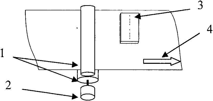

Image

  • Method for realizing high-speed following ink-jet printing by dynamically controlling print resolution
  • Method for realizing high-speed following ink-jet printing by dynamically controlling print resolution
  • Method for realizing high-speed following ink-jet printing by dynamically controlling print resolution

Examples


Embodiment 1

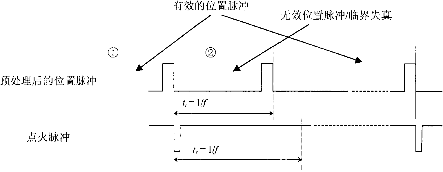
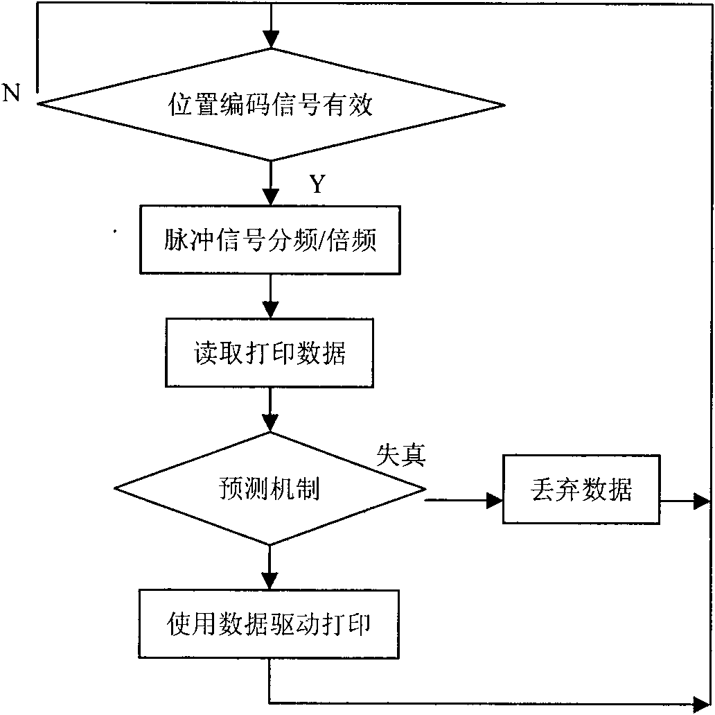
[0027] refer to Figure 1 ~ Figure 3 , a method for realizing high-speed follow-up inkjet printing by dynamically controlling printing resolution, said method comprising the following steps:

[0028] (1), collect the position pulse signal on the position encoder, control the ignition pulse signal of the printing head according to the position pulse signal;

[0029] (2), set the time between the next position pulse signal and the adjacent previous position pulse signal as t i ;The maximum firing frequency of the print head is f,t v = 1 / f; when t i v , it is determined that there is a risk of distortion, the latter position pulse signal is an invalid pulse signal, and the latter position pulse signal is discarded.

[0030] In this embodiment, the method for predicting the imminent printing geometric distortion: a prediction mechanism is designed to detect the critical moment when the printing geometric distortion is imminent.

[0031] The reason for the geometric distortion ...

Embodiment 2

[0038] In this embodiment, a window mechanism for reducing resolution is also designed to suppress the phenomenon of resolution jitter.

[0039] Due to the mechanical mechanism, there is often a narrow-band oscillation phenomenon with a fixed frequency in the relative motion speed. When the relative motion speed is at the critical value (v m ) around , this oscillation causes the distortion prediction mechanism to produce valid output periodically. The result is a noticeable periodic dithering of the print resolution over a small range.

[0040] A window mechanism with reduced resolution is introduced, and the window width Wd is based on the number of pulse signals output by the position encoder. It is stipulated that once the risk of distortion is predicted, it shall be handled according to the following steps:

[0041] e, actively reduce the resolution to 1 / 2 of the original value

[0042] f, unconditionally keep this lower resolution at least Wd

[0043] g, within this r...


PUM


Abstract

The invention relates to a method for realizing high-speed following ink-jet printing by dynamically controlling print resolution, which comprises the following steps: (1) collecting position pulse signals from a position encoder, and controlling ignition pulse signals of a printing head according to the position pulse signals; (2) setting the time ti between a next position pulse signal and an adjacently previous position pulse signal, and setting the maximal ignition frequency f of the printing head, wherein tv is equal to 1 / f; judging that distortion risk exists and the next position pulse signal is the idler pulse signal when t1 is smaller than tv; giving up the next position pulse signal, and temporarily lowering the print resolution. The invention can ensure that paper moves at high speed, and avoid image distortion.

Description

technical field [0001] The invention relates to a control method of postal printing equipment, in particular to a method for high-speed follow-up inkjet printing. Background technique [0002] Industrial printing equipment can achieve high-speed and large-volume printing tasks at a very economical price, but it is unable to solve the printing needs of data such as product serial numbers, production dates, ticket numbers, and anti-counterfeiting patterns. This type of data usually has the characteristics of dynamic changes page by page. A typical variable data printing scheme is to make the objects to be printed run continuously on the production line in sequence, and a set of printing equipment is fixedly installed on the side of the production line. Whenever an object passes through the printing area , a print job is automatically performed. The printing device mentioned here may be a set of inkjet or laser printing mechanisms, or it may be just a mechanical coding machine...

Claims


Application Information

Patent Timeline
IPC IPC(8): B41J2/205
Inventor 占红武胥芳
Owner ZHEJIANG UNIV OF TECH
Learn More