Method for recognizing a change in lane of a vehicle

a technology of lane change and vehicle, applied in the direction of instruments, digital computer details, and reradiation, can solve the problems of unambiguous lane change, inability to accurately determine the travel corridor, and malfunction of the regulating system

Inactive Publication Date: 2005-05-03
ROBERT BOSCH GMBH
View PDF8 Cites 397 Cited by
  • Summary
  • Abstract
  • Description
  • Claims
  • Application Information

AI Technical Summary

Benefits of technology

[0006]The object of the present invention is to provide a method which allows a lane change to be more accurately detected.
[0010]Since at higher traffic densities multiple vehicles traveling in front are generally simultaneously detected by the locating device, it is preferable to form a composite angular velocity from the measured relative angular velocities of several or all of the detected vehicles, for example by forming an average, or a weighted average based on the distance or angle. By assigning greater weight to vehicles which have only a slight angular deviation from the path of the subject vehicle, it is possible to reduce interference effects caused by the relative speeds of the vehicles traveling in front. Similarly, by assigning greater weight to vehicles only a small distance from the subject vehicle, interference effects which appear when entering into a curve are reduced. However, the noise from the angular signal of vehicles in close proximity is generally increased because of the motion of these same vehicles. To suppress such noise, in addition to information on the vehicles it is usually possible to also collect time-specific information. Since the radar measurements are typically repeated periodically in a fixed regulating cycle, information is provided over multiple regulating cycles, so that here as well, a lower weight may be assigned to the older cycles.
[0011]In addition, a plausibility effect may occur during the determination of the composite angular velocity. For example, for three or more vehicles which are being localized it may be practical to eliminate outliers whose angular velocity clearly deviates from the other vehicles. Thus, it is possible in particular to reduce interference effects caused by a lane change of one of the vehicles traveling in front. If only two vehicles traveling in front are within the locating range, generally a lane change by one of the vehicles traveling in front is assumed only if one of these vehicles starts to pass or completes the passing maneuver. These situations may be identified using data on the measured distance and relative angular velocity.
[0017]The lane change signal thus obtained may be used within the scope of an ACC system and in many other ways as well. In particular, the travel corridor of the subject vehicle may be appropriately adjusted during detection of the start of a lane change. It is also possible to take into account that at the midpoint of the lane change the direction of travel of the subject vehicle deviates from the direction of the roadway. The value of this angular deviation may be quantitatively determined by integrating the yaw rate signal, the composite angular velocity signal, or a combination of both over time, and may then be used to correct the predicted travel path and thus the travel corridor. In this manner it is possible to prevent the erroneous evaluation of stationary targets during the lane change. In one even simpler embodiment, this effect may also be achieved by reducing the penetration depth of the locating device so that objects farther away continue to be disregarded in the distance regulation.
[0019]Regulating systems are also known which detect the course of the roadway by evaluating a camera image or by using other sensors, and which assist the vehicle in staying within the lane (lane keeping support) by intervening in the steering of the vehicle. When the vehicle is equipped with such a system, it is possible not only to detect the lane change directly by evaluation of the sensor signals which sense the edge of the roadway, but in this case also to use the method according to the present invention for plausibility testing.

Problems solved by technology

In non-steady state situations, however, in particular during a lane change, an accurate determination of the travel corridor has proven to be difficult.
Merely evaluating the signal from the turn indicator is of no further use here, since actuation of the turn indicator only indicates the intention to change lanes but does not allow the detection of exactly when the lane change starts and ends.
Even making additional allowance for the steering commands of the driver does not enable the lane change to be unambiguously detected, since a curved roadway course may also give rise to the steering commands.
In the past, these uncertainties in the detection of a lane change have often caused malfunctions in the regulating system due to the fact that during the lane change the radar beam temporarily sweeps over the edge of the roadway and identifies stationary targets such as road signs or the like as presumably relevant objects, or that for roadways having three or more lanes, vehicles in the next-to-adjacent lane are erroneously associated with the travel corridor of the subject vehicle.

Method used


Image

  • Method for recognizing a change in lane of a vehicle
  • Method for recognizing a change in lane of a vehicle
  • Method for recognizing a change in lane of a vehicle

Examples


Embodiment Construction

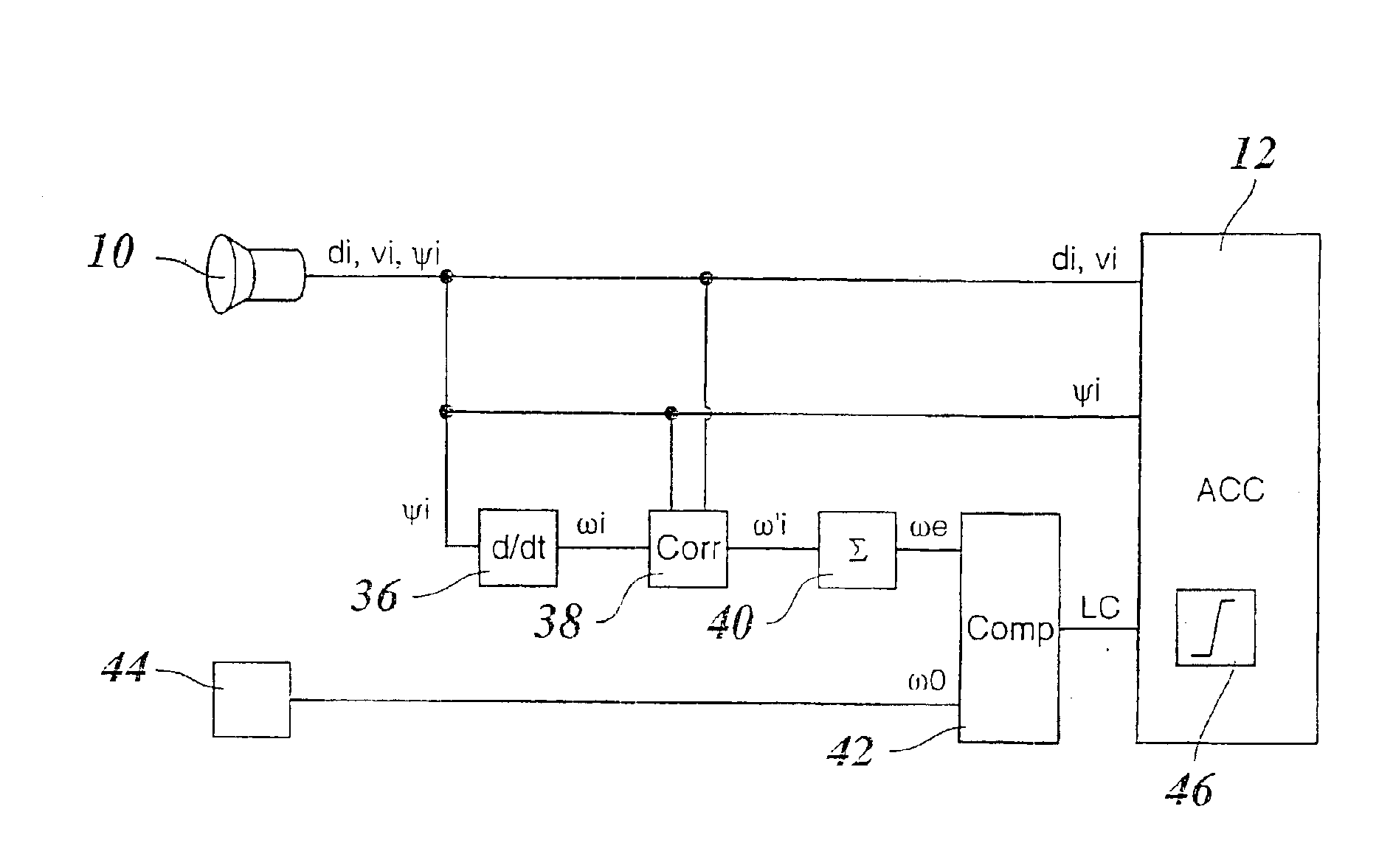
[0027]Because the design and operating principle of a distance- and speed-regulating system, referred to below as an ACC system, are known as such, FIG. 1 shows only those components of such a system that are important for understanding the present invention.

[0028]A radar sensor 10 is provided as a locating device for vehicles traveling in front, and is mounted on the front of the regulated vehicle and periodically locates target objects situated in front of the vehicle, for example vehicles traveling in front, and stationary targets on the edge of the roadway. By evaluating the radar echo, signals are produced, either in the radar sensor itself or in a processing unit connected downstream, which indicate the distance di, the relative speeds vi (in the radial direction), and the azimuth angles ψi of the located objects. The azimuth angles here are defined with respect to the instantaneous straight-ahead direction of the vehicle. Positive azimuth angles correspond to an angular devia...


PUM


Abstract

A method of detecting a lane change of a subject vehicle (20), having a locating device (10) which uses angular resolution for locating vehicles (VEH1, VEH2, VEH3) traveling in front, and a device (44) for determining the yaw rate (ω0) of the subject vehicle. The angular velocity (ωi) of at least one vehicle traveling in front relative to the subject vehicle (20) is measured using the locating device (10), and a lane change signal (LC) indicating the lane change is formed by comparing the measured angular velocity (ωi) to the yaw rate (ω0) of the subject vehicle.

Description

BACKGROUND INFORMATION[0001]The present invention relates to a method of detecting a lane change of a vehicle having a locating device which uses angular resolution for locating vehicles traveling in front, and a device for determining the yaw rate of the subject vehicle.[0002]Distance- and speed-regulating devices for motor vehicles, also referred to as ACC (adaptive cruise control) systems, are known. In these systems, objects, for example vehicles traveling in front in the same lane as the subject vehicle, are detected using a locating device, for example a radar system which provides angular resolution, which enables the distance and relative speed of the vehicle traveling in front to be measured. The capability for angular resolution in such a radar system has been used in the past to check the detected objects for plausibility, so that, for example, vehicles in the same lane as the subject vehicle may be distinguished from road signs or markings on the edge of the roadway, or ...

Claims


Application Information

Patent Timeline
Patent Type & Authority Patents(United States)
IPC IPC(8): B60K31/00G01S13/00G01S13/93B60W30/16G01S13/931
CPCB60K31/0008B60W30/16G01S13/931B60T2201/08B60T2201/081G01S2013/9346B60W2550/20G01S2013/9325G01S2013/9321B60W2520/14G01S2013/93185B60W2554/00B60W30/18145B60W2554/805
Inventor WINNER, HERMANNLUEDER, JENS
Owner ROBERT BOSCH GMBH
Why Eureka
Try Eureka