
Systems and methods for image resolution enhancement

Inactive Publication Date: 2007-04-12
UNIV OF CONNECTICUT
View PDF3 Cites 407 Cited by
  • Summary
  • Abstract
  • Description
  • Claims
  • Application Information

AI Technical Summary

Benefits of technology

[0014] Also disclosed is a method for enhancing a digital image, the method including: receiving the digital image; providing a plurality of directional cancellation masks for examining the image; using the plurality of masks, obtaining directional derivatives for features within the image; and filtering data from the digital image according to the directional derivatives to provide an enhanced digital image.
[0017] Not least of all, a method for enhancing the resolution of digital images is disclosed, the method including: obtaining a sequence of digital images of an object of interest; applying homomorphic transformation to estimate a point spread function (PSF) for a system producing the digital images; deblurring each image in the sequence to provide restored images; registering the restored images; and processing the restored images with an anisotropic diffusion super-resolution reconstruction (ADSR) technique to provide images having enhanced resolution.

Problems solved by technology

On the other hand, ultrasound imaging often has insufficient spatial resolution for many applications and is generally corrupted by speckle noise.
These problems significantly affect interpretation of the images.
However, these techniques are all based on original image resolution and do not have sub-pixel resolving capability.
In fact, with use of these techniques, the actual spatial resolution is worsened by the suppression of noise.
One problem is that higher frequency ultrasound has difficulty penetrating into deeper tissue.
However, large apertures require more complicated front-end circuitry.
The limitation of the nature and technology limits the use of ultrasound imaging, for example, it can only be used as a screening tool instead of diagnostic tool in breast tumor imaging.
These techniques do not provide sub-pixel information.
Even though the method achieves positive results to a certain degree, it is computationally demanding and the results are no better than most other methods.
Although the theory of the approach was well founded, in an actual implementation, the method blurs the edges and produces artificial maximums, which could be misinterpreted as structures.
The results are very impressive; however, the isotropic regularization used in the algorithm limits the effectiveness of the process.

Method used


Image

  • Systems and methods for image resolution enhancement
  • Systems and methods for image resolution enhancement
  • Systems and methods for image resolution enhancement

Examples


Embodiment Construction

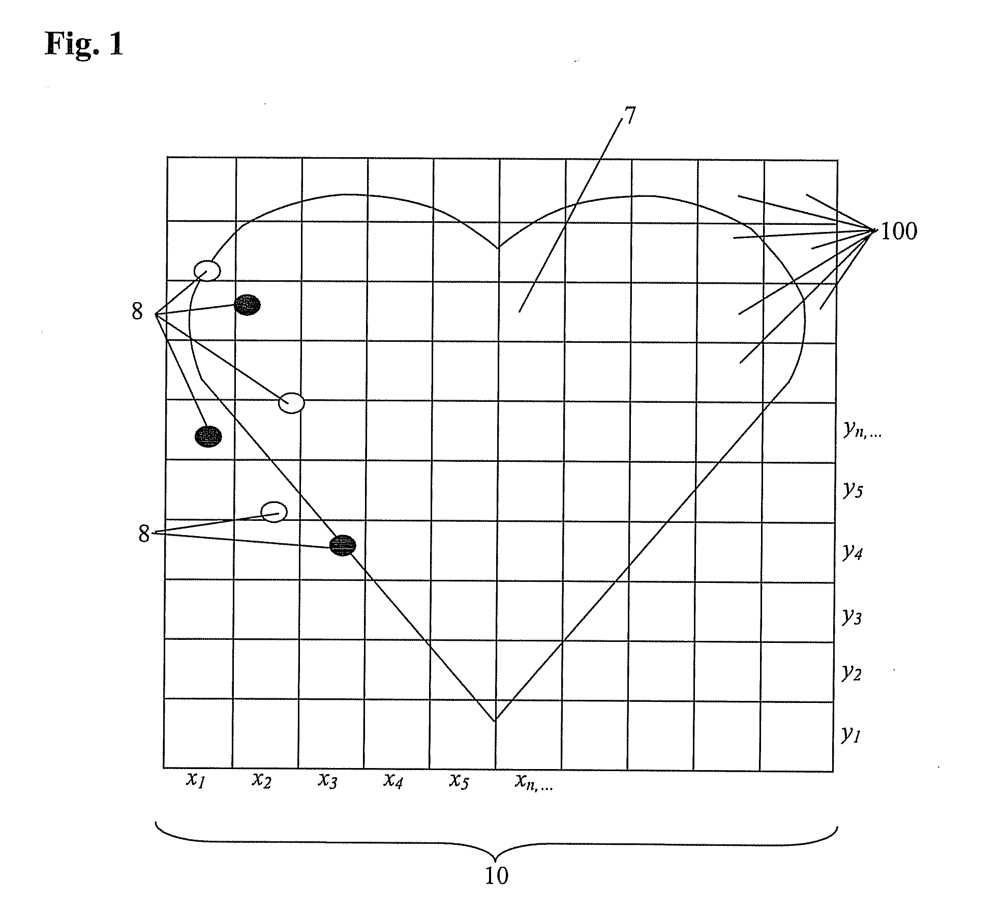
[0065] Referring now to FIG. 1, there is shown an illustration of components of an image 10 of a target 7. The image 10 includes a plurality of pixels 100. Each of the pixels 100 includes image information including at least one of a grey scale value and a color value for the region defined by the respective pixel 100. The aggregation of the plurality of pixels 100 having image information provides for the depiction of the target 7 as (in the form of) the image 10. Included in the exemplary illustration of FIG. 1 are various image defects, referred to as “speckle 8.” In the embodiment depicted, the plurality of pixels 100 is arranged in a two-dimensional array wherein each of the pixels 100 has an x-coordinate and a y-coordinate. Each image 10 includes a plurality of pixels 100, and is a “digital image.” That is, the image 10 is an assembly of digitized data included in each of the pixels 100. Other forms of images, such as analog forms, may be converted into digital format using te...


PUM


Abstract

A system for providing enhanced digital images includes an image receiving device for accepting at least one digital image and obtaining digital information therefrom; a computer program product comprising machine readable instructions stored on machine readable media, the instructions for providing enhanced digital images by performing upon the at least one digital image at least one of: a minimum directional derivative search, a multi-channel median boosted anisotropic diffusion, an non-homogeneous anisotropic diffusion technique and a pixel compounding technique.

Description

CROSS REFERENCE TO RELATED APPLICATIONS [0001] This application is filed under 37 CFR 1.53(b) and claims benefit of an earlier filing date under 35 U.S.C. §119(e) to U.S. Provisional Patent Application 60 / 712,024, filed Aug. 26, 2005, the entire disclosure of which is hereby incorporated by reference herein in its entirety.BACKGROUND OF THE INVENTION [0002] 1. Field of the Invention [0003] This invention relates to enhancement of digital images by reduction of noise and provision of resolution enhancement. [0004] 2. Description of the Related Art [0005] Among the modern medical imaging modalities, ultrasound is a well known approach that is low-cost, portable, and real-time operable. It has been widely used in clinical testing and diagnosis. On the other hand, ultrasound imaging often has insufficient spatial resolution for many applications and is generally corrupted by speckle noise. These problems significantly affect interpretation of the images. How to enhance the visibility of...

Claims


Application Information

Patent Timeline
IPC IPC(8): A61B8/00
CPCA61B8/00G06T3/4053G06T5/50G06T2207/10136G06T2207/20221G06T2207/30004
Inventor YANG, ZHIFOX, MARTIN D.RAUNIG, DAVID L.ANALOUI, MOSTAFATUTHILL, THERESA
Owner UNIV OF CONNECTICUT
Learn More