Filter sealing system

一种过滤器罩、密封件的技术,应用在空气过滤器进行保养领域,能够解决小制造公差、连接、增加成本等问题

Active Publication Date: 2007-02-14
MANN HUMMEL GMBH
View PDF1 Cites 6 Cited by
  • Summary
  • Abstract
  • Description
  • Claims
  • Application Information

AI Technical Summary

Problems solved by technology

The disadvantage here is that for fastening on the housing surface of the filter element, the inner surface of the frame structure must not deviate in diameter from the outer diameter of the housing surface, otherwise a connection would occur between the raw side and the clean side of the filter element
Therefore, extremely tight manufacturing tolerances must be maintained here on the sides of the frame structure and the sides of the filter element housing, which of course increases costs

Method used


Image

  • Filter sealing system

Examples


Embodiment Construction

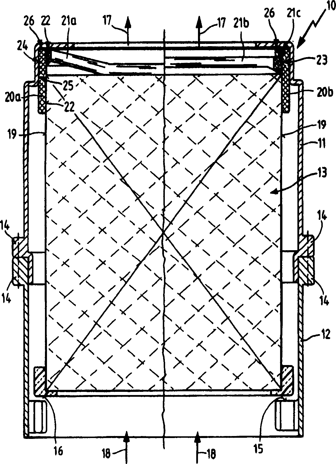
[0017]The single figure shows an air filter 10 having an upper filter housing part 11 and a lower filter housing part 12 with a filter element 13 arranged therein. The filter element 13 is an axially flow-through filter element with mutually closed axially extending channels. As filter medium, paper, synthetic material or a felt is preferably specified here. The upper and lower filter housing parts 11 , 12 are connected to each other by a connecting mechanism 14 . Here, for example, the connection mechanism may be a clip, a screw or other detachable connection methods known in the prior art. In the lower region of the lower filter housing part 12 , the filter housing forms an axial stop 15 which serves to axially support and fix the filter element 13 when the two filter housing parts 11 , 12 are assembled. Correspondingly, on the lower end face of the filter element 13 in the region of the axial stop 15 is formed a preferably circumferential stop damper 16 . The retaining d...


PUM


Abstract

The invention relates to a filter element for a fluid stream flowing in at the front side, in which a machine for sealing an inflow and an outflow side of the filter element in a filter housing part includes an annular sealing part. A peripheral seal in the form of an annular collar is provided on a frontal side of the filter element, connected via an axial section of the element casing surface. Part of the collar extends axially over the frontal side of the element, and a frame element is connected with an axial protuberant portion of the collar. As a result, the frame element supports the collar against forces acting radially outwards.

Description

technical field [0001] The invention relates to an air filter element according to the preamble of claim 1 . Furthermore, the invention relates to a method according to the preamble of claim 11 for servicing an air filter with an air filter element according to the invention. Background technique [0002] Filter elements with axial flow through are used in many areas in which a gas or a liquid is to be filtered. Furthermore, these elements can be used in any type of filter housing and must be replaced or cleaned as required after reaching a certain load or after prescribed maintenance intervals. EP1159052 shows a filter element with a frame structure which is annularly connected to the housing surface of the filter element in the region of one of the end faces and has an extension which protrudes axially beyond the end face . On the extension, a sealing element is also arranged, which element is positioned at least partially around the outer peripheral surface of the exte...

Claims


Application Information

Patent Timeline
Patent Type & Authority Applications(China)
IPC IPC(8): B01D46/52
CPCB01D2275/10B01D46/525B01D2271/027
Inventor D·阿梅泽德S·弗勒克P·特劳特曼
Owner MANN HUMMEL GMBH
Why Eureka
Try Eureka