
Bottom roll bearing block

A technology of bearing seat and lower roller, which is applied in the direction of bearing components, shafts and bearings, rigid supports of bearing components, etc., to achieve the effect of solving the tension between the wire and mother, facilitating installation and maintenance, and improving the service life of the machine

Inactive Publication Date: 2007-02-14
王小建 +1
View PDF0 Cites 0 Cited by
  • Summary
  • Abstract
  • Description
  • Claims
  • Application Information

AI Technical Summary

Problems solved by technology

[0005] The beneficial effect of the present invention is that, compared with the existing lower roller bearing seat, it is more convenient for installation and maintenance, solves the problem of existing wire nuts and improves the service life of the machine

Method used


Image

  • Bottom roll bearing block
  • Bottom roll bearing block
  • Bottom roll bearing block

Examples


Embodiment Construction

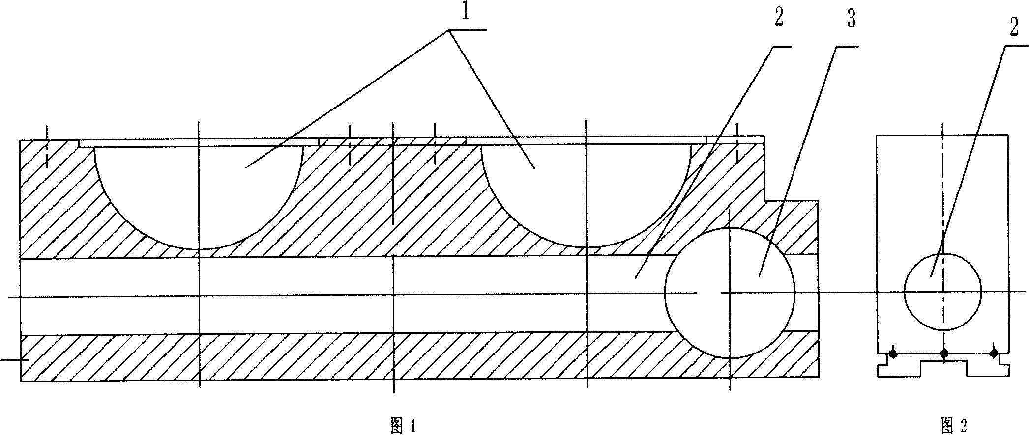
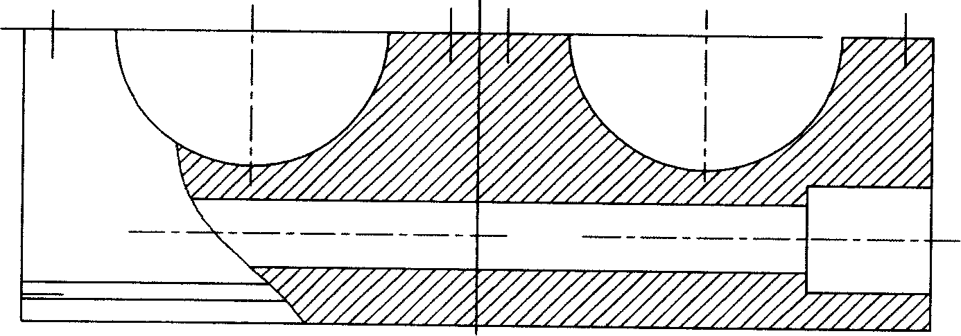
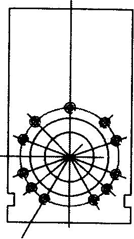
[0010] The present invention will be further described below in conjunction with the accompanying drawings. As shown in Fig. 1 and Fig. 2, the present invention discloses a lower roller bearing housing, the upper part of which is provided with a groove 1 or a round hole, and a tie bar perpendicular to the groove or round hole is arranged under the groove or round hole. Hole 2, one end or the middle of the tie rod hole is provided with a hole 3 perpendicular to it. The hole 3 and the tie rod hole 2 can be vertically intersected horizontally or vertically. There is a rod-shaped nut and a pull rod in the hole. Assembling, because there is a certain room for movement, there will be no tension in the pull rod nut during work, thereby improving the service life of the machine.


PUM


Abstract

A bearing base of bottom roller is prepared as setting groove or round hole at top of bearing base, setting drawbar under groove or round hole and making them be parallel to each other, setting hole at one end of drawbar and making hole be vertically crossed with drawbar.

Description

technical field [0001] The invention relates to a component of a plate rolling machine, in particular to a lower roller bearing seat. Background technique [0002] The existing lower roller bearing housing is generally provided with a groove or a round hole for bearing, and a hole perpendicular to the groove or the hole is arranged under the groove or the hole, and a nut position is arranged at one end of the hole and It is equipped with nuts, and the nuts are fixed by bolts, which move the bearing seat to adjust the position of the lower roller or the center distance of the screw. The hole is installed on the outer wall of the hole. Due to the influence of various factors, there is often a phenomenon of tension between the screw rod and the bearing seat, and sometimes even the end cover is pulled out, which directly affects the use and life of the machine. Contents of the invention [0003] In order to solve the deficiencies of the existing products, the invention provid...

Claims


Application Information

Patent Timeline
IPC IPC(8): F16C35/00B21D5/14
Inventor 王小建田衍新
Owner 王小建
Features
  • Generate Ideas
  • Intellectual Property
  • Life Sciences
  • Materials
  • Tech Scout
  • Unparalleled Data Quality
  • Higher Quality Content
  • 60% Fewer Hallucinations
Learn More