Pressure trigger luminous pen

A light-emitting pen, pressure technology, applied in the direction of instrument, electrical digital data processing, data processing input/output process, etc., can solve problems such as operation failure, increased motion friction, unable to move the pen head linkage tube, etc., to achieve response Sensitive, avoid misoperation effect

Inactive Publication Date: 2007-02-14
鲍炜
View PDF2 Cites 13 Cited by
  • Summary
  • Abstract
  • Description
  • Claims
  • Application Information

AI Technical Summary

Benefits of technology

This technology allows for reliable electrical connection between two parts - an electronic part called a controller chip located inside the pen's body and another part attached outside the housing on top. When there is no externally applied force against this part, the pen has its own springs power source but cannot detect if someone tries to use it without them. If they try to touch these buttons while pressing down their finger instead of typing directly into characters, then the pens will send out lights accordingly. By doing this, users have more flexibility than traditional types of writing tools due to how much space they require.

Problems solved by technology

This patented technical problem addressed by this patents relates to improving the accuracy and reliability of detecting touch input from a laser pointer without being affected negatively by external factors like gravity.

Method used


Image

  • Pressure trigger luminous pen
  • Pressure trigger luminous pen

Examples


Embodiment Construction

[0013] The present invention will be further described below in conjunction with the accompanying drawings and embodiments.

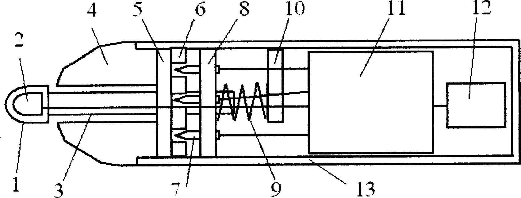
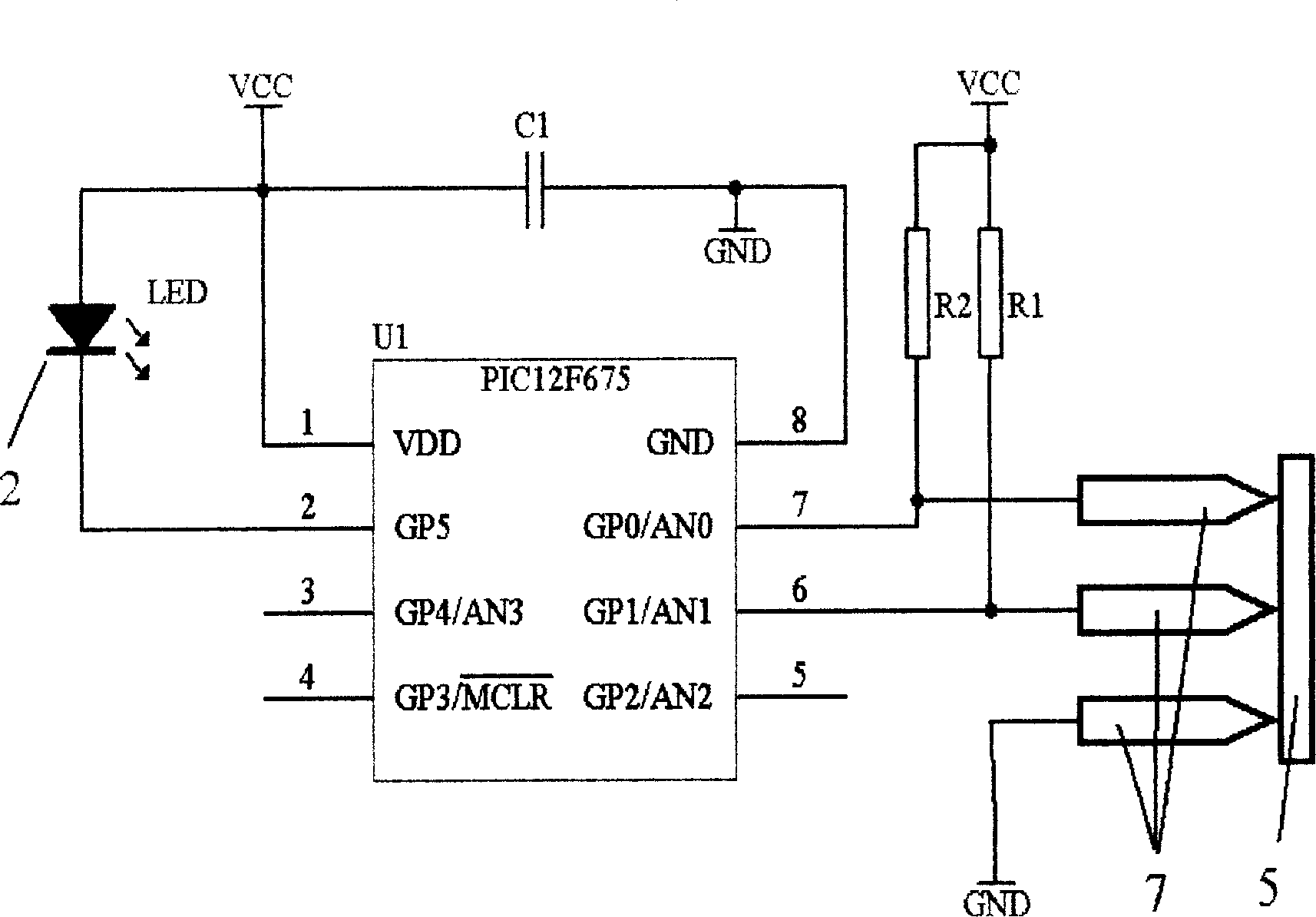
[0014] figure 1 A schematic structural cross-sectional view of a specific embodiment of the pressure-triggered luminous pen according to the present invention is given. A light-emitting device 2 is installed in the nib cap 1, the front end of the nib linkage tube 3 is connected to the nib cap 1, and the rear end is fixedly connected to the stylus disk 8, and three stylus 7 are fixedly installed on the stylus disk 8. The three contact pins are distributed in a triangular shape and point to the direction of the conductive disc. The conductive disc 5 is a disc with a surface conduction, which is fixed on the rear end face of the nib 4 . One end of spring 9 is pressed on the stylus disk 8, and the other end is pressed on the spring baffle 10, when nib cap is not subjected to external force, the pressure of spring 9 makes three stylus 7 all contact conducti...


PUM


Abstract

A pen with light being triggered on by pressure is prepared as firm-jointing one of contact pin disc and conduction disc to coupled tube at pen head and another one being erected at back end of pen mouth, fixing three conductive contact pins being distributed in triangle arrangement and pointing them to conduction disc, pressing one end of spring on contact pin disc firm-jointed with coupled tube of pen head, setting internal diameter of pen mouth to be greater than external diameter of coupled tube of pen head and connecting said contact pins to control circuit board through wire.

Description


Claims


Application Information

Patent Timeline
Owner 鲍炜
Why Eureka
Try Eureka