Overflow valve with magneto-rheological pilot valve

A technology of magnetorheological and pilot valves, which is applied in the direction of valve operation/release devices, valve details, safety valves, etc., which can solve the problems of easy heating, increased viscosity of magnetorheological fluids, and high cost, and achieve rapid reset action response , expand the scope of application, enhance the effect of working ability

Inactive Publication Date: 2015-05-20
HUAQIAO UNIVERSITY
View PDF6 Cites 24 Cited by
  • Summary
  • Abstract
  • Description
  • Claims
  • Application Information

AI Technical Summary

Problems solved by technology

At present, hydraulic valves based on magnetorheological technology generally have two deficiencies. One is the use of magnetorheological fluid as the working medium, and magnetorheological fluid is composed of a liquid continuous phase and a solid particle dispersed phase. The cost is high, so it is not suitable to be used in large quantities as the working medium of hydraulic transmission; second, the magnetorheological valve only includes one working gap, and the viscosity of the magnetorheological fluid increases when the valve operates, and it will bear a large load when flowing through the gap. Viscous resistance to adjust the opening pressure of the pilot spool, but when the valve is in the reset stroke, the liquid is still in the magnetic field and maintains high viscosity, which makes the reset stroke also bear large viscous resistance, which will cause the valve to fail to reset in time or the reset action to lag Significantly increased response time of hydraulic valves

Method used


Image

  • Overflow valve with magneto-rheological pilot valve

Examples


Embodiment Construction

[0018] The present invention will be further described below in conjunction with the accompanying drawings and specific embodiments.

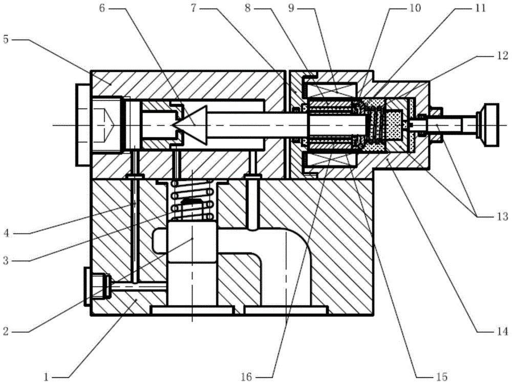
[0019] refer to figure 1 , a relief valve using a magneto-rheological pilot valve. The working medium in the relief valve is ordinary hydraulic oil. The working medium inside is magnetorheological fluid, and the volume of magnetorheological fluid is 30-150ml.

[0020] The overflow valve using a magnetorheological pilot valve includes a relief valve body 1, an upper cover plate 5 of the overflow valve, a main valve core 2, a main valve core spring 3, and a magnetorheological pilot valve cone valve 6 , Magnetorheological pilot valve front cover 7, magnetorheological pilot valve body 14, magnetorheological pilot valve piston 8, electromagnetic coil 9, pressure regulating spring 12, pressure regulating block and pressure regulating screw 13.

[0021] The upper cover plate 5 of the overflow valve, the front cover plate 7 of the magneto-rheological...


PUM


Abstract

An overflow valve with a magneto-rheological pilot valve comprises an overflow valve seat, an overflow valve upper cover plate, a main valve spool, an overflow valve body, a main valve spool spring, a magneto-rheological pilot cone valve, a magneto-rheological pilot valve front cover plate, a magneto-rheological pilot valve body, a magneto-rheological pilot valve piston, an electromagnetic coil, a one-way valve plate, a transition plate, a pressure regulating spring, a pressure regulating block and a pressure regulating screw. The overflow valve upper cover plate, the magneto-rheological pilot valve front cover plate and the magneto-rheological pilot valve body are mounted on the overflow valve seat, a valve rod of the magneto-rheological pilot cone valve penetrates the overflow valve upper cover plate, enters the magneto-rheological pilot valve body and is closely connected with the magneto-rheological pilot valve piston, the magneto-rheological pilot valve piston, the magneto-rheological pilot valve body and the electromagnetic coil form a working gap, so that magneto-rheological fluid flows, a space is formed between the transition plate and the valve rod of the magneto-rheological pilot cone valve, the one-way valve plate can elastically deform in the space, and the pressure regulating screw is rotated and can push the pressure regulating block at the front end of the pressure regulating screw to compress or release the pressure regulating spring.

Description

technical field [0001] The invention relates to an overflow valve using a magneto-rheological pilot valve, which belongs to the technical field of hydraulic transmission. technical background [0002] Relief valve is a kind of pressure control valve widely used in hydraulic transmission system. Its main function is to adjust the working pressure of hydraulic system. Its structure includes direct acting type and pilot type. Pilot type relief valve is suitable for systems with high circuit pressure. The opening pressure of the relief valve is achieved by adjusting the preload of the pilot valve spring by rotating the screw behind the pilot valve spool. It is characterized by convenient and flexible adjustment, but the pressure control range is limited, and it is impossible to realize real-time pressure adjustment and automatic, programmed and intelligent adjustment. Magneto-rheological fluid is a kind of "smart material" with controllable viscosity. Under normal conditions, i...

Claims


Application Information

Patent Timeline
Patent Type & Authority Applications(China)
IPC IPC(8): F16K31/06F16K17/20
CPCF16K17/20F16K31/0644
Inventor 刘晓梅李洪友
Owner HUAQIAO UNIVERSITY
Why Eureka
Try Eureka