Hydraulic power pulse oil displacement experimental facility and experimental method thereof

A technology of hydraulic pulse and experimental device, which is applied in the direction of vibration generating device, earthwork drilling, mining fluid, etc., and can solve the problems affecting the effect of hydraulic pulse equipment, total energy loss, etc.

Active Publication Date: 2011-02-16
CHINA UNIV OF PETROLEUM (EAST CHINA)
View PDF3 Cites 40 Cited by
  • Summary
  • Abstract
  • Description
  • Claims
  • Application Information

AI Technical Summary

Problems solved by technology

China University of Petroleum (East China) has also done related work on hydraulic pressure pulse equipment in the last century, but its hydraulic pulse equipment is deployed at the wellhead of the oil production well, and the hydraulic pulse needs to be transmitted to the downhole through the annular liquid, so the hydraul

Method used


Image

  • Hydraulic power pulse oil displacement experimental facility and experimental method thereof
  • Hydraulic power pulse oil displacement experimental facility and experimental method thereof
  • Hydraulic power pulse oil displacement experimental facility and experimental method thereof

Examples


Embodiment 1

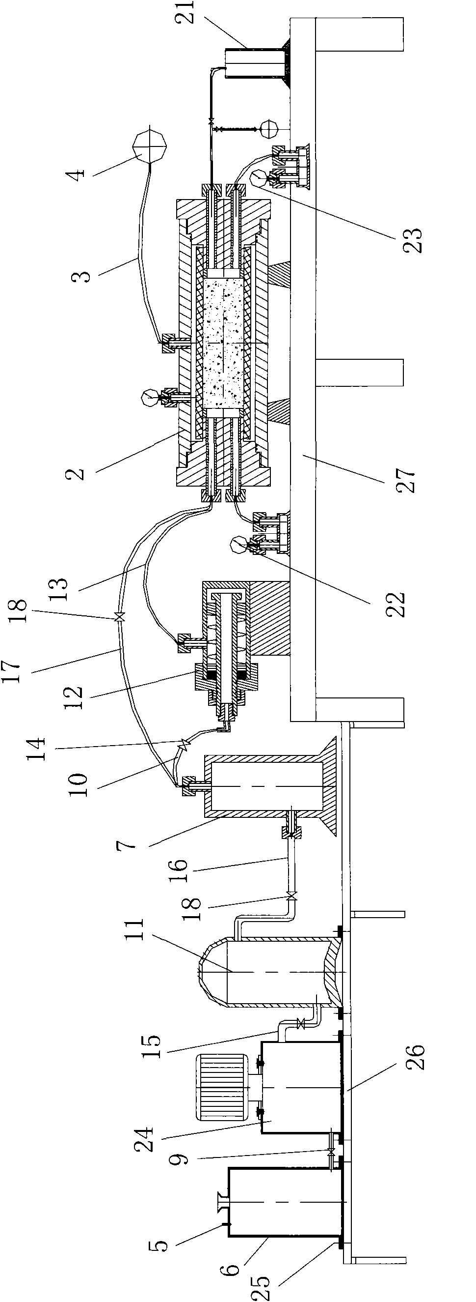
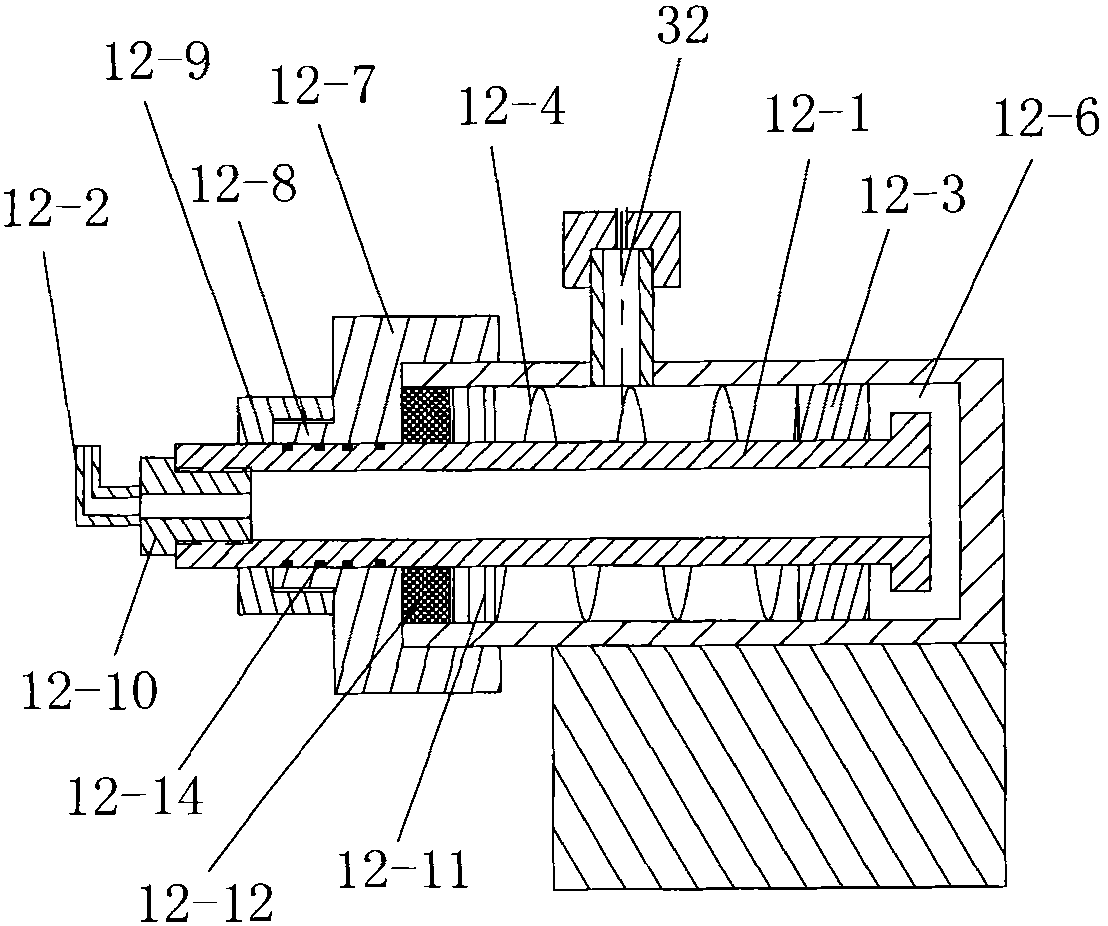
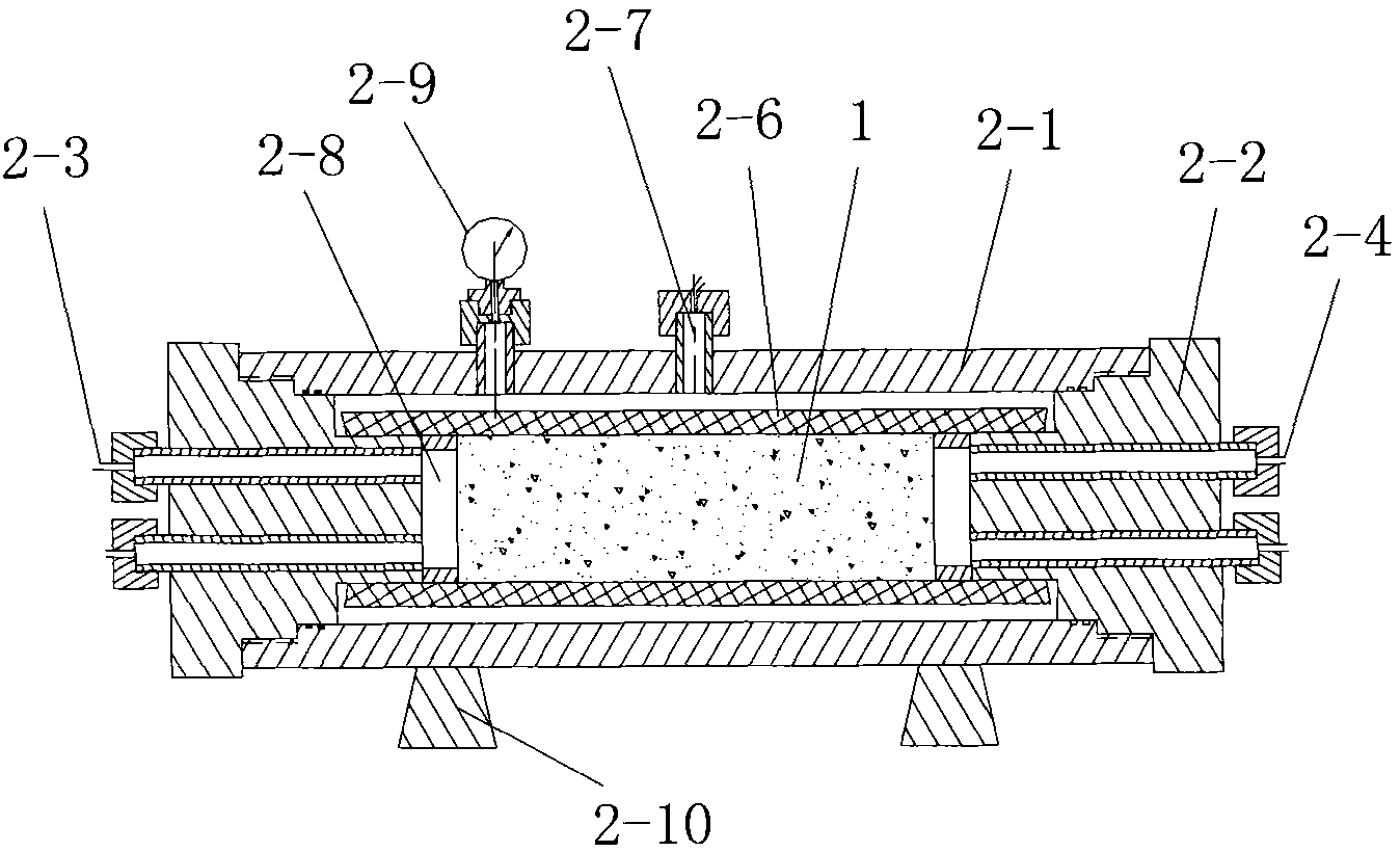
[0075] Such as figure 1 , Figure 4 The hydraulic pulse flooding experimental device shown includes a core holder 2 for holding the tested core 1, a thermostat arranged outside the core holder 2, and a hydraulic pipe 3 connected to the core The annular pressure interface of the holder 2 is connected and the annular pressure supply device 4 and the hydraulic pulse wave generating device 12, which apply annular pressure to the tested rock core 1 clamped inside the core holder 2, pass through the water pipeline respectively. The oil pipeline is connected to the liquid inlet of the core holder 2, and the water storage tank and the oil storage tank of the simulated formation water and the simulated formation oil are respectively installed inside, and the liquid outlet through the external pipeline and the core holder 2 A liquid container with a connected mouth, the liquid container is marked with a scale for measuring the volume of the solution stored in it, the water pipeline and...

Embodiment 2

[0113] Such as Figure 6 As shown, in this embodiment, the difference from Embodiment 1 is that the liquid inlet of the core holder 2 is connected to the chemical reagent preparation tank 29 through the chemical reagent delivery pipeline 28, and the chemical reagent delivery pipeline 28 The chemical reagent delivery control valve 30 and pumping equipment 31 are installed on the top, and the chemical reagent delivery pipeline 28, the chemical reagent preparation tank 29, the chemical reagent delivery control valve 30 and the pumping equipment 31 respectively form a chemical flooding experimental device. The oil test device and the hydraulic pulse flooding test device described in Example 1 jointly constitute a hydraulic pulse-chemical flooding test device. In this embodiment, the hydraulic pulse flooding experimental device used is exactly the same as that in Embodiment 1. Both the chemical reagent delivery control valve 30 and the pumping device 31 are controlled by the contr...


PUM


Abstract

The invention discloses a hydraulic power pulse oil displacement experimental facility and an experimental method thereof. The experimental facility comprises a core clamping device, an annular pressure supply device, a hydraulic power pulse wave generating device, a water storage tank and an oil storage tank which are connected with the liquid inlet of the core clamping device by virtue of a water pipeline and an oil pipeline as well as a liquid container which is connected with the liquid outlet of the core clamping device; wherein the water pipeline and the oil pipeline are all provided with an intermediate container, a pumping device used for generating high pressure liquid flow and an energy storage tank. The experimental method includes the following steps: firstly, oil displacementexperiment is carried out under the condition that no hydraulic power pulse is added; secondly, oil displacement experiment is carried out while frequency and amplitude hydraulic power pulse wave of core are replaced, and meanwhile hydraulic power pulse auxiliary chemical oil displacement experiment is completed; thirdly, data processing is carried out. The invention has reasonable design, mounting convenience, simple operation and good simulation effect, can improve efficiency of oil displacement by water and crude oil recovery ratio, and experiment of hydraulic pulse wave oil displacement and hydraulic pulse wave auxiliary reservoir core oil displacement by water can be realized.

Description

technical field [0001] The invention belongs to the technical field of dynamic physical simulation experiments of enhanced oil displacement in an oil production chamber, and in particular relates to a hydraulic pulse displacement experimental device and an experimental method. Background technique [0002] Nowadays, the research and application of vibratory oil recovery technology is progressing rapidly, and there has been a lot of consensus in practice. Some research work has been carried out in China, mainly represented by the high-power ground seismic source developed by the Institute of Engineering Mechanics of the National Earthquake Administration and Jilin Oilfield. Ultrasonic downhole generator developed by University of Petroleum and Sichuan University, etc. China University of Petroleum (East China) has also done related work on hydraulic pressure pulse equipment in the last century, but its hydraulic pulse equipment is deployed at the wellhead of the oil productio...

Claims


Application Information

Patent Timeline
IPC IPC(8): E21B43/25E21B43/22E21B43/20E21B43/26E21B28/00
Inventor 蒲春生张更吴飞鹏
Owner CHINA UNIV OF PETROLEUM (EAST CHINA)
Why Eureka
Try Eureka