
Signal modulating method, demodulating method and signal modulating apparatus and demodulating apparatus

A technology of signal modulation and signal demodulation, applied in the direction of recording signal processing, using self-timed codes for signal processing, information storage, etc., can solve only one, bad influence of servo system stability bit error rate, can not fully suppress modulation Signal low-frequency components and other issues, to achieve the effect of suppressing low-frequency components

Inactive Publication Date: 2007-02-21
SONY CORP
View PDF1 Cites 0 Cited by
  • Summary
  • Abstract
  • Description
  • Claims
  • Application Information

AI Technical Summary

Problems solved by technology

[0032]However, there are only 3 types of 2-bit boundary bits. In addition, due to limitations such as travel, the boundary bits that can often be inserted are limited to only 1 type
Therefore, in the prior DSV control method, there are many intervals where DSV control cannot be performed. As a result, the low-frequency components of the modulation signal cannot be sufficiently suppressed, which will affect the stability of the servo system and the bit error rate during data demodulation. produce adverse effects

Method used

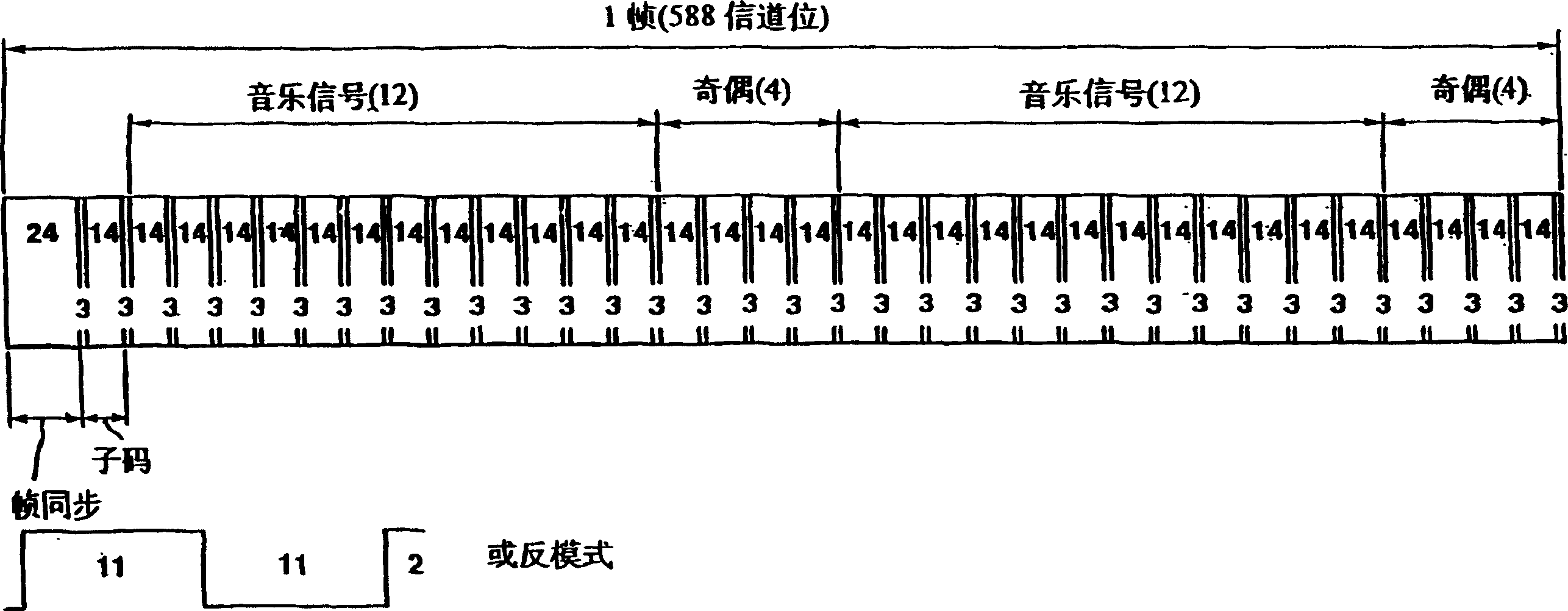
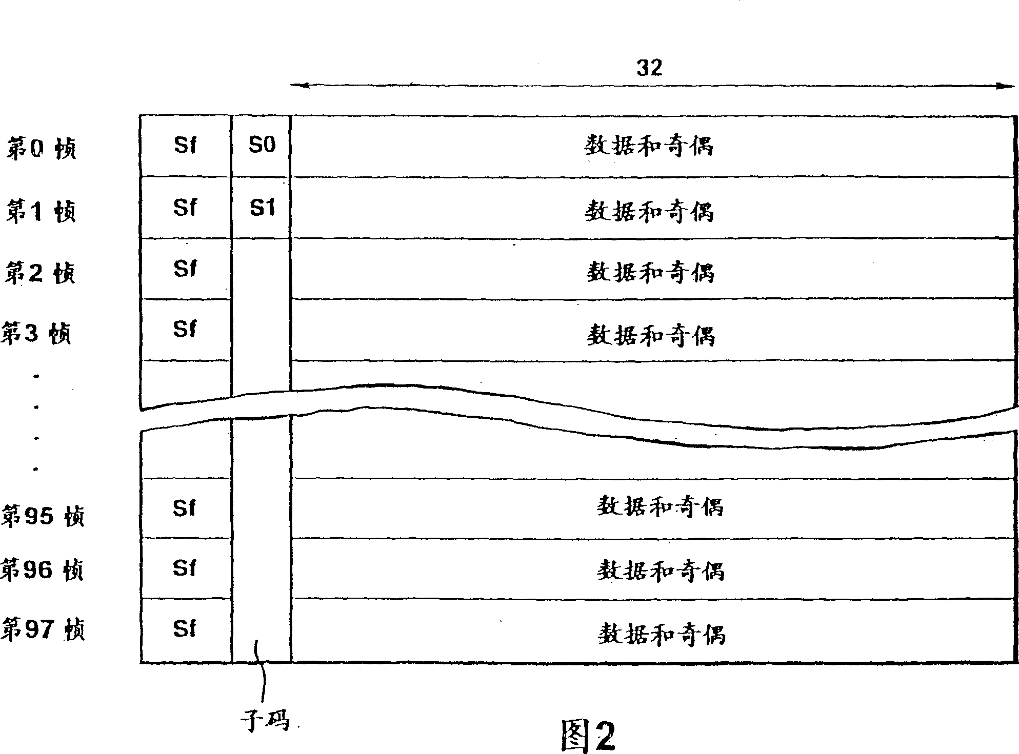
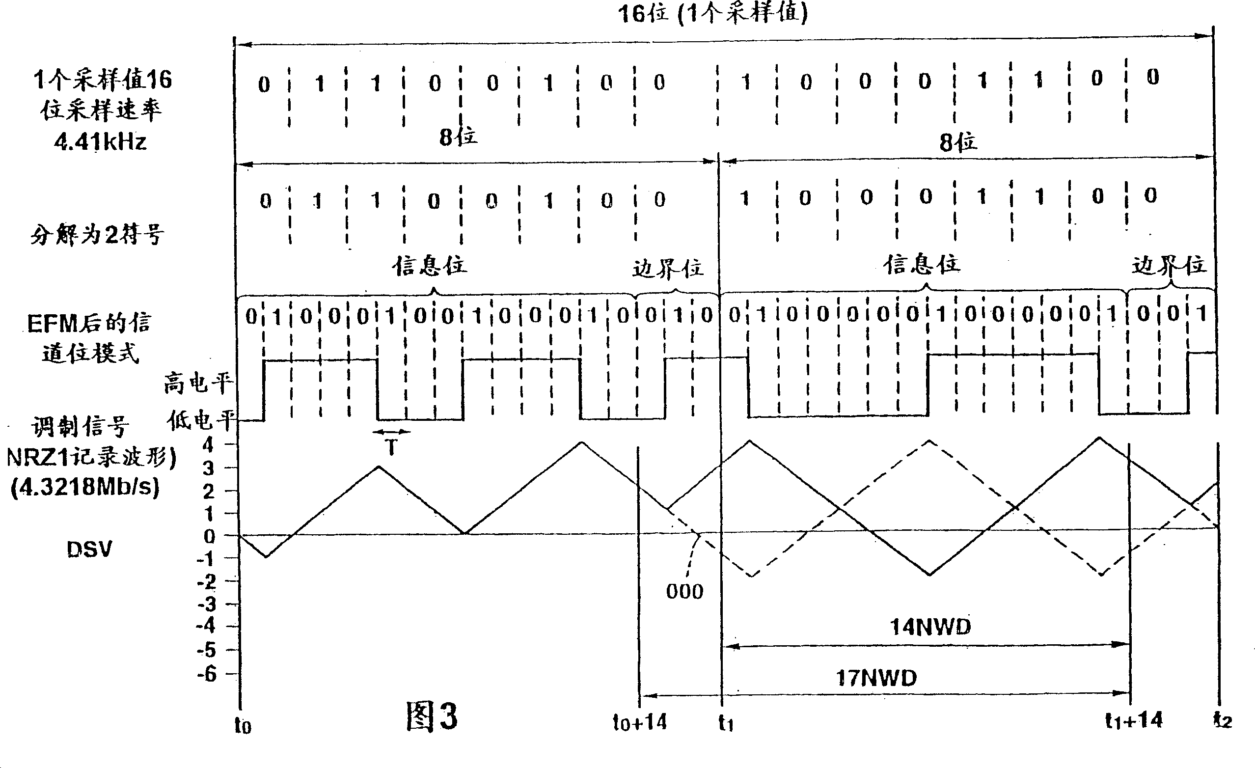

Image

  • Signal modulating method, demodulating method and signal modulating apparatus and demodulating apparatus
  • Signal modulating method, demodulating method and signal modulating apparatus and demodulating apparatus
  • Signal modulating method, demodulating method and signal modulating apparatus and demodulating apparatus

Examples


Embodiment Construction

[0054] Embodiments of the signal modulation method, signal modulation device, signal demodulation method, and signal demodulation device of the present invention will be described below with reference to the accompanying drawings.

[0055] The signal modulation method and the signal modulation device of the present invention are to convert the data string of the input M-bit unit into the code string of the N-bit unit respectively (however, M and N are integers, M

[0056] An example of such a conversion table is show...


PUM

PropertyMeasurementUnit
thicknessaaaaaaaaaa

Abstract

The present invention uses a conversion table a part of which is duplexed in order to directly convert input M-bit data into an N-bit code without using a margin bit. This conversion table comprises first and second sub-tables each including a plurality of code groups, and these code groups contain different codes to the same input data. In the second sub-table, a part of the first sub-table obtaining by allocating different codes to the data ranging from the first input data to the second input data of the sub-table is duplexed. The set of the codes of the duplexed portion of the conversion table is so constituted as to take a digital sum variation of opposite signs, and codes are sequentially allocated to the input data from the code having the greater absolute value of the digital sum variation. In this way, the present invention can appropriately suppress low frequency components of modulation signals.

Description

[0001] This application has an application date of July 7, 1995, a divisional submission date of March 31, 2004, an application number of 200410032439.9, and an invention title of "Signal modulation method, signal modulation device, signal demodulation method, and signal demodulation" Device" is a divisional application of the invention patent application. technical field [0002] The present invention relates to a signal modulation method, a signal modulation device, a signal demodulation method, and a signal demodulation device used when recording or reproducing digital signals such as digital audio signals, digital image signals, and data, for example, on a recording medium. A signal modulation method, a signal modulation device, a signal demodulation method, and a signal demodulation device for an optical disc device dedicated to reproduction, or a recording and reproduction device for a recordable or rewritable optical disc. Background technique [0003] When digital si...

Claims


Application Information

Patent Timeline
Patent Type & Authority Applications(China)
IPC IPC(8): G11B20/10G11B20/14H03M7/00H03M5/14H03M7/14H03M7/20H03M7/46H03M13/00H03M13/09H03M13/31H04L25/49
CPCH03M7/46H03M5/14G11B2020/1465G11B2020/1461H03M5/145G11B20/1426H03M13/31G11B2020/1473G11B20/10
Inventor 冈崎透吉村俊司
Owner SONY CORP
Learn More