
Axial-gap motor/generator

An axial gap, generator technology, applied in synchronous motors with static armatures and rotating magnets, electrical components, electromechanical devices, etc., can solve problems such as unsatisfactory, and achieve the effect of improving cooling performance

Inactive Publication Date: 2007-02-28
NISSAN MOTOR CO LTD
View PDF0 Cites 2 Cited by
  • Summary
  • Abstract
  • Description
  • Claims
  • Application Information

AI Technical Summary

Problems solved by technology

[0003] However, with this conventional technology, since the output lead-out wire as a heat source is drawn out from only one side of the stator, the heat source is concentrated only on one side of the stator, and strong heat is generated only on one side, from the motor / generator From a cooling performance standpoint, this is highly undesirable

Method used


Image

  • Axial-gap motor/generator
  • Axial-gap motor/generator
  • Axial-gap motor/generator

Examples


Embodiment Construction

[0016] The most preferred embodiments of the present invention will be described below with reference to the accompanying drawings.

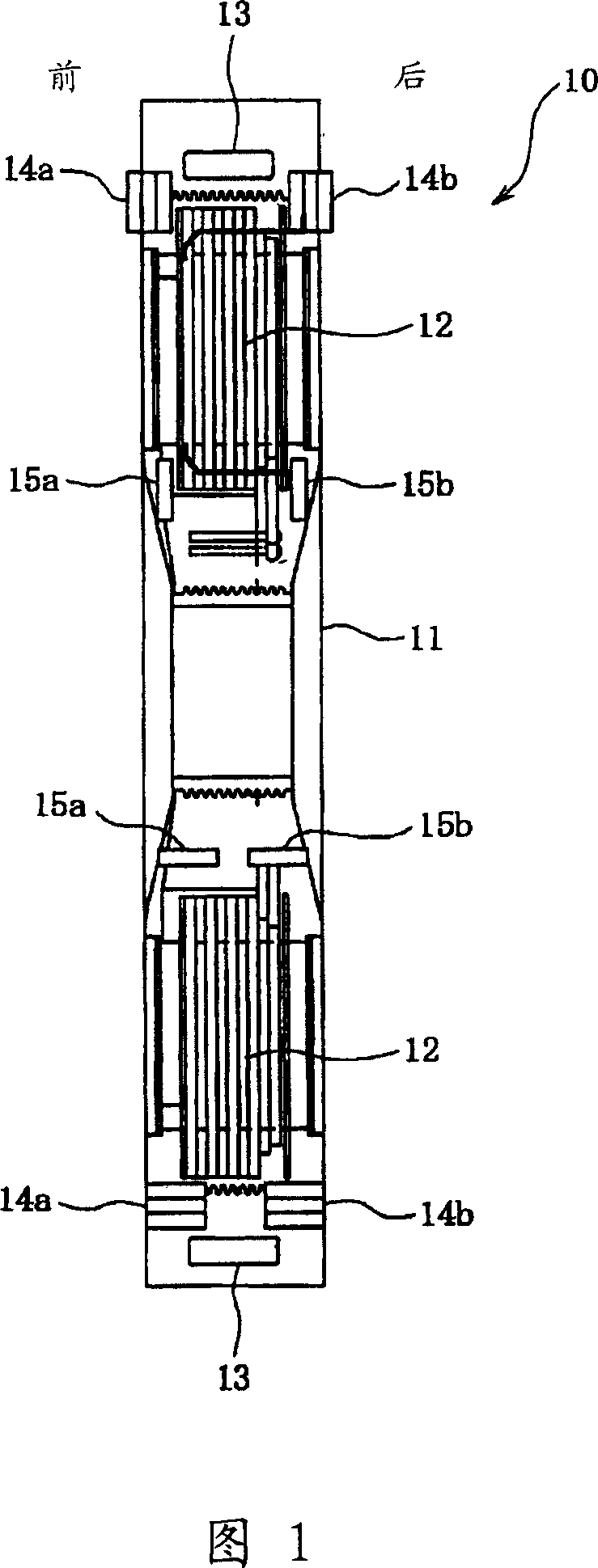
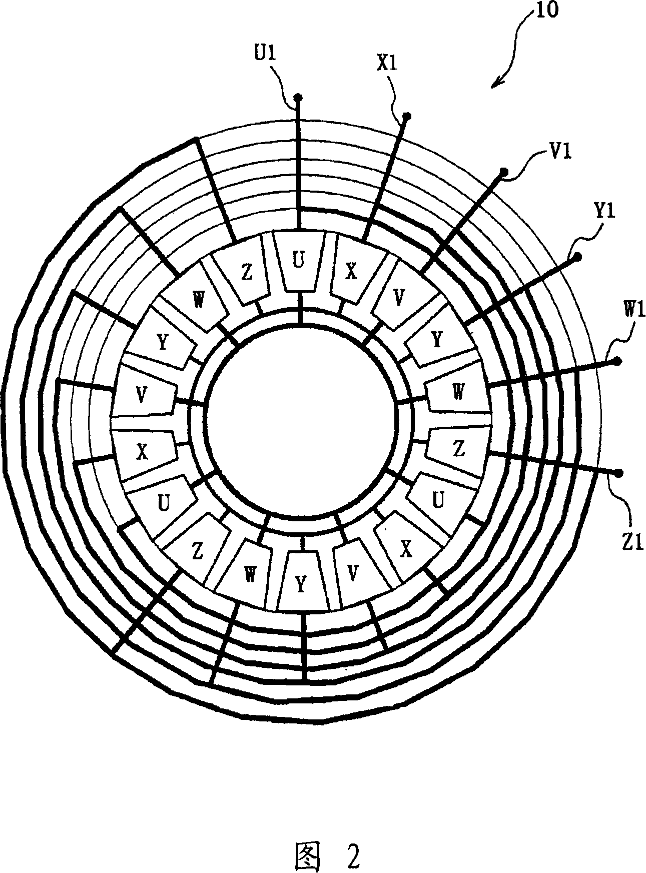
[0017] Fig. 1 shows a schematic cross-sectional view of a stator for an axial gap motor / generator according to an embodiment of the present invention, and Fig. 2 shows a wire joint structure for the axial gap motor / generator shown in Fig. 1 top view.

[0018] As shown in FIGS. 1 and 2, a stator 10 of an axial gap motor / generator includes a stator core 11 formed in a toric shape and positioned around a motor / generator rotation axis (not shown in the drawings), and includes a plurality of Coils 12 (see FIG. 1 ) of winding wires arranged in a row along the circumferential direction of the stator core 11, wherein the coils 12 are equipped with U-phase coils, V-phase coils, W-phase coils, X-phase coils, Y-phase coils, and Z-phase coils. 3 of each type of coil. Thus, the coil 12 consists of 6 phases and 18 slots (see FIG. 2 ). In addition, the wate...


PUM


Abstract

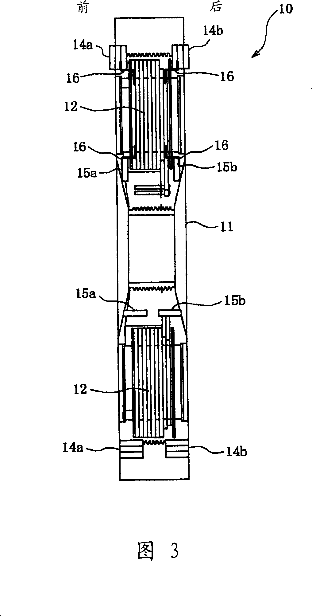
An axial-gap motor / generator that has a stator equipped with a plurality of polyphase coils from which are led output lead wires, wherein wire connectors 16 for each of coil 12 are divided and arranged on the front side and rear side of the side surface of stator 10.

Description

technical field [0001] The present invention relates to an axial gap motor / generator, and more particularly to a wire connection structure of an axial gap motor / generator comprising a stator with polyphase coils. Background technique [0002] Conventional technology is known for axial gap motor / generators comprising a stator with multiphase coils consisting of, for example, 6 phases. This axial gap motor / generator has a set consisting of 3 output leads X1, Y1 and Z1 which lead from a wire connection structure for a three-phase coil on one side; and contains 3 output Another group of leads U1, V1 and W1, these output leads from the three-phase coils on the other side, and output leads from these two groups only from one side of the stator. [0003] However, with this conventional technology, since the output lead-out wire as a heat source is drawn out from only one side of the stator, the heat source is concentrated only on one side of the stator, and strong heat is generate...

Claims


Application Information

Patent Timeline
IPC IPC(8): H02K5/22
CPCH02K21/24H02K3/50
Inventor 涩川佑一西山幸广
Owner NISSAN MOTOR CO LTD
Learn More