Solar heat dissipation distribution network ring main unit

A solar energy and ring main unit technology, which is applied in the details of substation/switch layout, electrical components, cooling/ventilation of substation/switchgear, etc., can solve the problems of single function, poor anti-interference ability, poor heat dissipation efficiency, etc. Improve overall efficiency, improve heat dissipation effect, improve heat dissipation and cooling performance

Pending Publication Date: 2018-11-23
STATE GRID JIANGSU ELECTRIC POWER CO LTD TAIZHOU POWER SUPPLY BRANCH +1
View PDF0 Cites 1 Cited by
  • Summary
  • Abstract
  • Description
  • Claims
  • Application Information

AI Technical Summary

Problems solved by technology

[0002] The distribution network ring main unit is one of the infrastructures of the distribution network, which is used to install and protect various important distribution components. With the continuous advancement of the upgrading and transformation of the domestic distribution network, the intelligent and efficient distribution network To match it, all kinds of precision electronic components are also continuously added to the entire grid structure. The detection and feedback of these precision components to the overall environment of the grid have greatly improved the intelligence and efficiency of grid management. The operation of the power grid is smoother and safer, but at the same time, these components usually require high precision in design and use, and their ability to resist external interference is poor. Therefore, a relatively stable power grid environment and a suitable operating environment are required. The existing distribution network ring network cabinet , in order to achieve this purpose, a fan is usually installed on the cabinet to cool down, but its structure is simple, the function is single, and the heat dissipation efficiency is poor, and the purpose of cooling and heat dissipation can only be achieved when the power grid is working normally

Method used


Image

  • Solar heat dissipation distribution network ring main unit
  • Solar heat dissipation distribution network ring main unit

Examples


Embodiment Construction

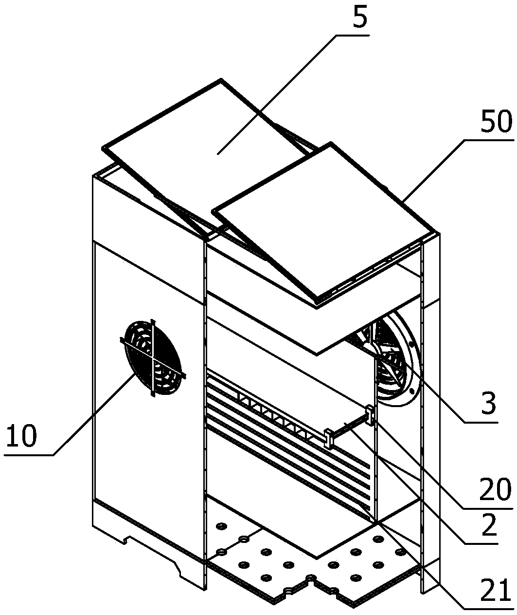
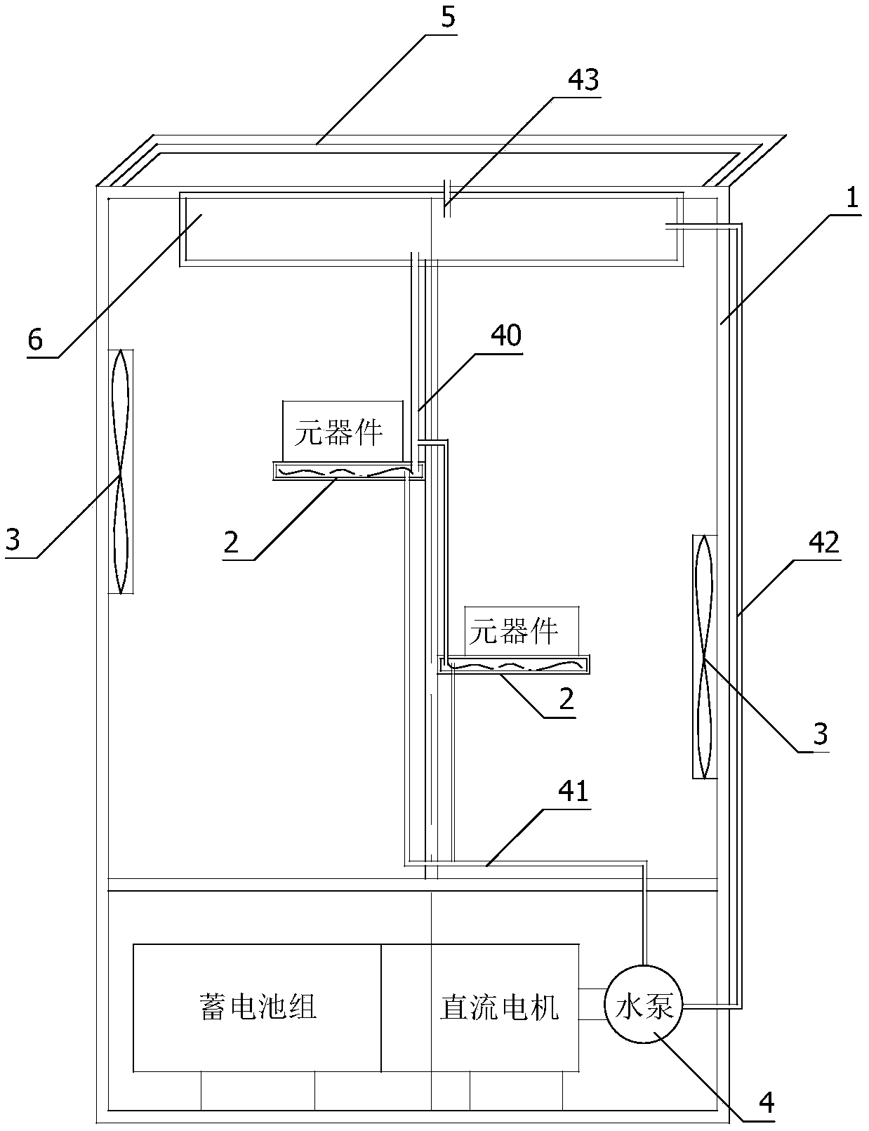
[0016] A solar heat dissipation distribution network ring network cabinet of the present invention is mainly used to solve the problem of heat dissipation and cooling of various distribution network ring network cabinets in the distribution network during use. The heat dissipation effect is better, and the water-cooled heat dissipation scheme with better heat dissipation effect is adopted. Based on this scheme, the present invention can adopt a targeted heat dissipation scheme to cool down the components with different heat dissipation requirements separately, and use components that require better cooling effect Installed on the first mounting board for contact cooling to ensure the normal operation of such components, and other components with lower cooling requirements are arranged in different positions on the first mounting board or its vicinity according to different requirements. The purpose of this treatment One is to try to ensure those components that need cooling eff...


PUM


Abstract

The invention belongs to the field of power grid supporting equipment, and particularly relates to a solar heat dissipation distribution network ring main unit. According to the ring main unit, a targeted heat dissipation scheme can be adopted, and components with different heat dissipation requirements can be cooled separately; the components needing a relatively high cooling effect are installedon the first installation board for contact cooling, so that normal work of the components can be guaranteed, while the components with relatively low cooling requirements are arranged on the first installation plate or at different positions near to the first installation plate according to different needs, so that the special cooling requirements of the components can be guaranteed to the greatest extent; in addition, the utilization efficiency of resource is better improved more reasonably; and meanwhile, the requirements of low-temperature resources are reduced, and addition of unreasonable cooling loads and areas is avoided, so that the best cost performance can be achieved under the condition of relatively low resource supply.

Description

technical field [0001] The invention belongs to the field of power grid supporting equipment, and in particular relates to a solar heat dissipation distribution network ring main unit. Background technique [0002] The distribution network ring main unit is one of the infrastructures of the distribution network, which is used to install and protect various important distribution components. With the continuous advancement of the upgrading and transformation of the domestic distribution network, the intelligent and efficient distribution network To match it, all kinds of precision electronic components are also continuously added to the entire grid structure. The detection and feedback of these precision components to the overall environment of the grid have greatly improved the intelligence and efficiency of grid management. The operation of the power grid is smoother and safer, but at the same time, these components usually require high precision in design and use, and thei...

Claims


Application Information

Patent Timeline
IPC IPC(8): H02B1/56H02B1/32
CPCH02B1/32H02B1/565
Inventor 李珩许颖文陈彦莹吴健
Owner STATE GRID JIANGSU ELECTRIC POWER CO LTD TAIZHOU POWER SUPPLY BRANCH
Why Eureka
Try Eureka