
Cooling plate and cooling system

A cooling system and cooling plate technology, which is applied in the direction of cooling devices, furnace cooling devices, furnace cooling, etc., can solve the problems of unsuitable fluid technology, costly processing technology of cooling plate parts or guard plates, etc., and achieve improved cooling performance and improved Cooling water flow performance and small pressure loss effect

Inactive Publication Date: 2005-11-23
SMS DEMAG AG
View PDF0 Cites 0 Cited by
  • Summary
  • Abstract
  • Description
  • Claims
  • Application Information

AI Technical Summary

Problems solved by technology

[0003] The first type of bending of the cooling plate part or the cover plate and the provision of grooves in this curved cover plate are expensive in terms of processing technology.
In addition, the cooling channel with a roughly "lens-shaped" groove section formed by the groove shape of the two cooling plates is not suitable for fluid technology

Method used


Image

  • Cooling plate and cooling system
  • Cooling plate and cooling system
  • Cooling plate and cooling system

Examples


Embodiment Construction

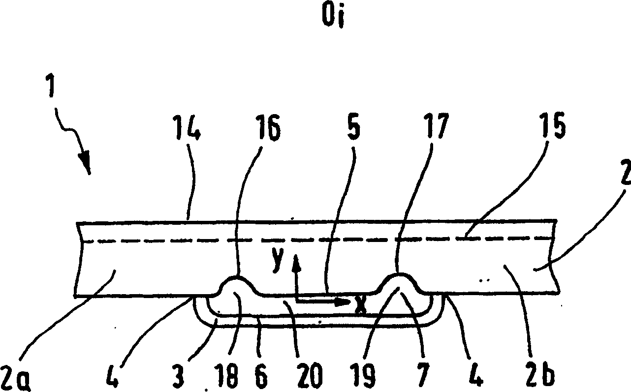
[0028] figure 1 represents a cooling plate 1 or furnace wall plate, which has a first pointing toward the furnace interior O i The first cooling plate part 2 and the second cooling plate part 3 are welded to each other on the back side. The weld seam 4 is located on the protected cold side of the cooling plate or furnace wall. Between the water side back of the first cooling plate part 2 as a rolled copper billet and the water side 6 of the second cooling plate part 3, a cooling channel 7 is formed, which leads to a cooling medium, preferably cooling water . The pipe sections 8 , 9 are fitted in holes in the second cooling plate part 3 for the inflow and outflow of water. The fixing of the cooling plate 1 on the furnace wall 10 is carried out, for example, by means of a connecting plate 11, which is inserted into a support 12 mounted on the furnace wall and braked by means of a pin 13 (see Figure 4 ). The first cooling plate part 2 is designed as a solid rolled blank wit...


PUM


Abstract

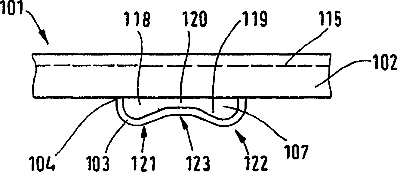
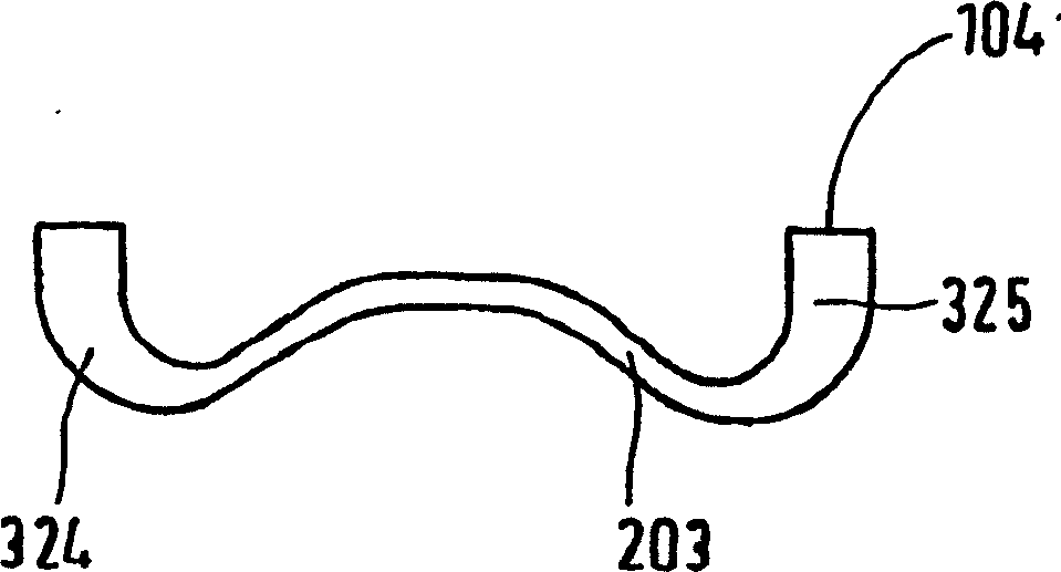
The invention relates to a cooling plate (1, 101) for a shaft furnace provided with a refractory lining. Said shaft furnace comprises a first laminated cooling plate element (2, 102) which is oriented towards the inside of the furnace (Oi), a second laminated rear cooling plate element (3, 103) which is welded to the first element, a cooling channel (7, 107) arranged between the first and second cooling plate elements, and tube sections (8, 9) to the cooling agent inlet or the cooling agent outlet. The aim of the invention is to improve the production, flow and cooling properties. To this end, the first cooling plate element (2, 102) is embodied in the form of a bloom having a plane front side (14) facing the inside of the furnace (O1), and the cross-sectional surface of the cooling channel is larger than in the central region (20; 120), in relation to the longitudinal extension of the cross-section in the end regions (18, 19; 118, 119). The invention also relates to a cooling plate system (33).

Description

technical field [0001] The invention relates to a cooling plate for a shaft furnace equipped with a refractory lining, in particular for a blast furnace, which has a first rolling cooling plate part pointing towards the interior of the furnace and a second rolling rear Cooling plate parts, which are welded to each other, also have a cooling channel formed between the first and second cooling plate parts and pipe sections for the inlet of the cooling medium or the outflow of the cooling medium. Here both the first and the second cooling plate part are made of copper or a low-alloyed copper alloy. Furthermore, the invention also relates to a cooling system. Background technique [0002] A cooling plate of the above-mentioned type is described in German patent 100 00 987.5. This patent discloses a cooling plate for a shaft furnace provided with a refractory lining, which has a cooling channel which can be acted upon by a cooling medium, wherein at least the front side facing ...

Claims


Application Information

Patent Timeline
IPC IPC(8): C21B7/10F27B1/24F27D1/12F27D9/00
CPCF27D2009/0048F27D2009/0051F27B1/24C21B7/10F27D2009/0045F27D2009/0062F27D1/12F27D2009/0013
Inventor E·科尔比克P·海因里希D·比恩巴赫
Owner SMS DEMAG AG
Learn More