Bi-directional friction clutch assembly for electric motors to prevent backdrive

A technology of clutch assembly and reverse transmission, which is applied in one-way clutches, automatic clutches, clutches, etc., and can solve problems such as reduced efficiency

Inactive Publication Date: 2007-03-07
SIEMENS VDO AUTOMOTIVE CORP
View PDF0 Cites 2 Cited by
  • Summary
  • Abstract
  • Description
  • Claims
  • Application Information

AI Technical Summary

Problems solved by technology

However, this also has a negative effect as the overall system is also less efficient and may require a larger motor

Method used


Image

  • Bi-directional friction clutch assembly for electric motors to prevent backdrive
  • Bi-directional friction clutch assembly for electric motors to prevent backdrive
  • Bi-directional friction clutch assembly for electric motors to prevent backdrive

Examples


Embodiment Construction

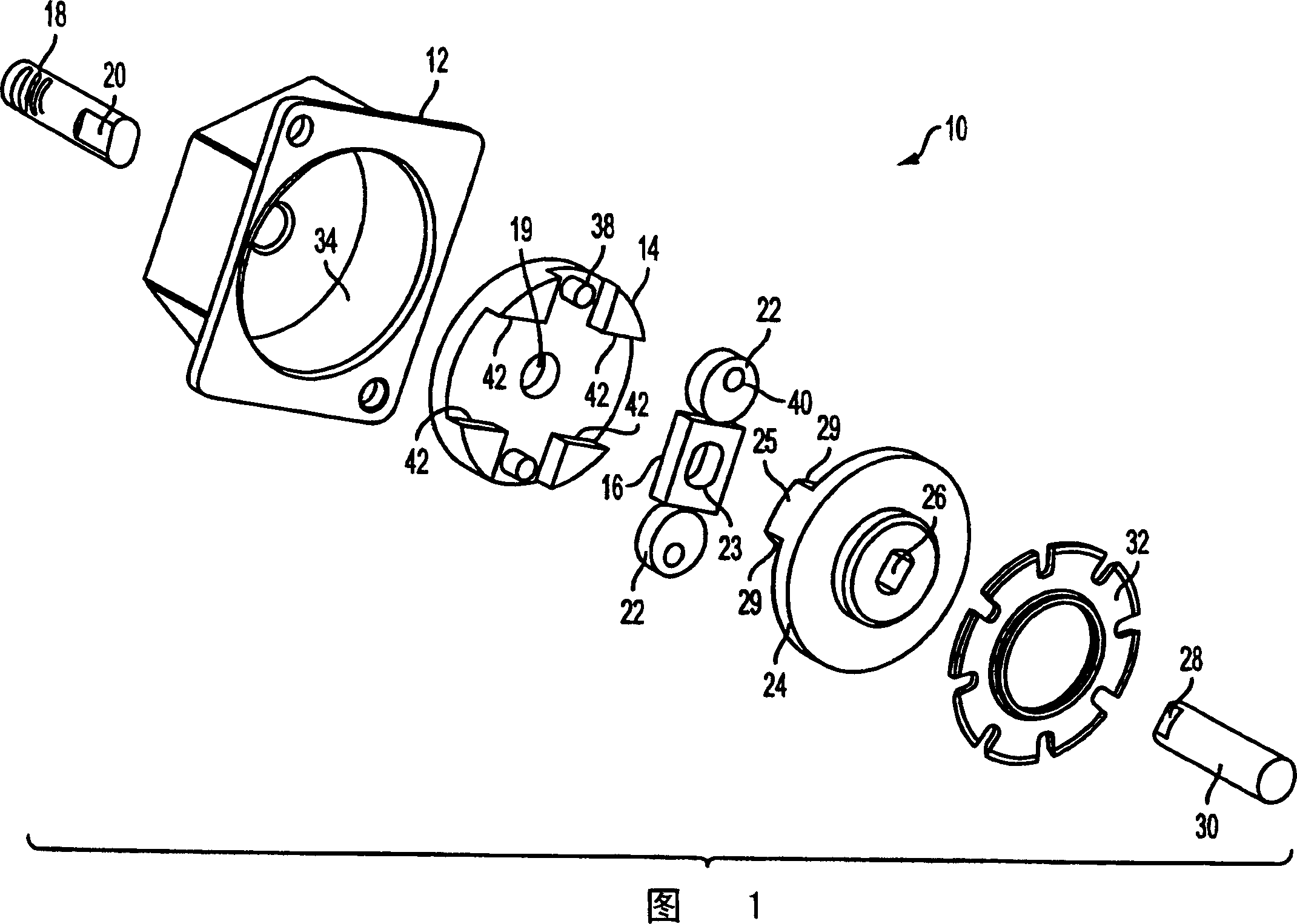
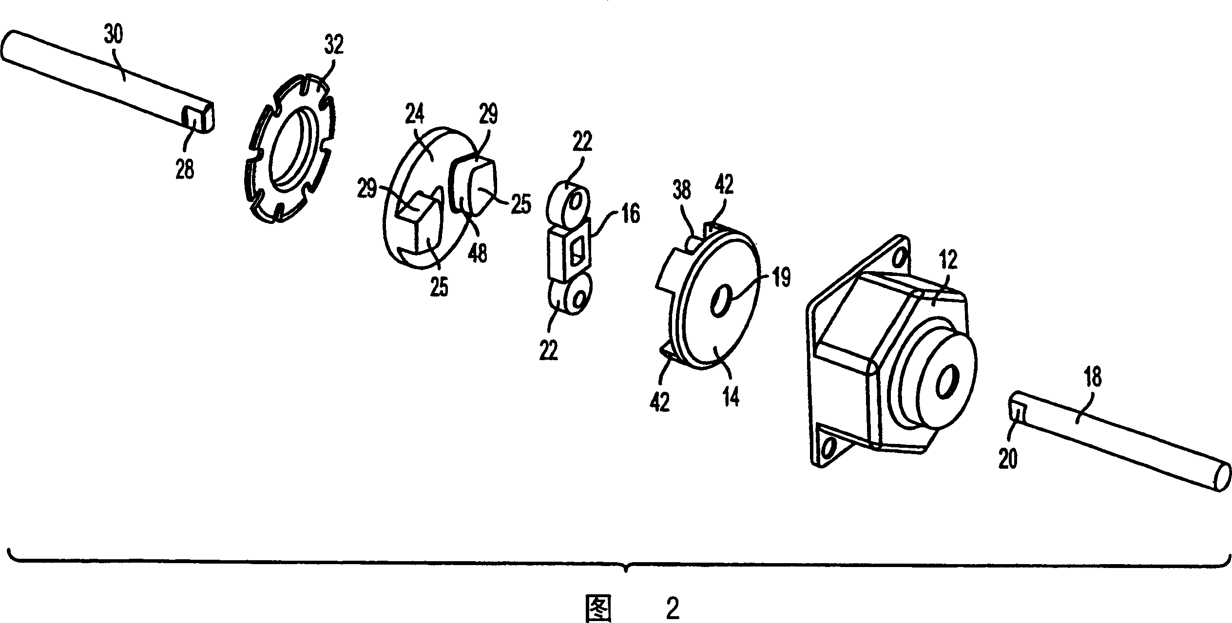
[0021] A clutch assembly in accordance with the principles of the present invention is indicated at 10 in FIG. 1 . The clutch assembly 10 includes a clutch housing 12 having an inner annular surface 34, a support plate 14, a cam 23 having a keyhole 23 to fit over the end 20 of the worm shaft 18, a cam follower associated with the cam 16 22, a coupling 24 having a keyhole 26 to fit the end 28 of the shaft 30 of the motor armature (not shown), and for securing the support plate, cam and follower and coupling to the clutch housing The seat ring 32 in 12. Referring to Figure 5, the clutch assembly 10 may be mounted to the housing 36 of an electric motor, such as a conventional window regulator motor for a vehicle, such that the worm shaft 18 meshes with the conventional drive gear of the electric motor.

[0022] The support plate 14 can also be considered a clutch plate and includes a central hole 19 allowing the worm shaft 18 to pass therethrough. Additionally, the support plat...


PUM


Abstract

A clutch assembly (100) is provided for a motor having an armature shaft and a worm shaft having a worm constructed and arranged to engage a gear. The clutch assembly (100) includes a clutch housing (112) including a race surface (132); a cam (117) coupled to the worm shaft; follower structure (122) operatively associated with the cam; a clutch plate (114), and a clutch coupler (118) associated with the clutch plate, the cam, and the follower structure. The coupler is coupled to the armature shaft for rotation therewith, such that rotation of the coupler rotates the clutch plate, the cam and follower structure, and thus the worm shaft. During a back drive condition of the motor, when torque is transmitted to the worm shaft and thus to the cam, the cam is constructed and arranged to causes the follower structure (122) to contact and exert pressure on the race surface (132) thereby preventing rotation of the worm shaft.

Description

[0001] related application [0002] This application is based on U.S. Provisional Application No. 60 / 547833, filed February 26, 2004, and U.S. Provisional Application No. 60 / 551713, filed March 10, 2004, which are hereby claimed in Apply for rights first. technical field [0003] The present invention relates to a two-way clutch assembly for an electric motor, the clutch is activated (engaged) whenever the output shaft side becomes the driving element. Background technique [0004] In a motor with a worm and a worm gear, when an external torque acts on the output end of the worm gear assembly, it is necessary to prevent the worm and the worm gear from forming a reverse transmission. When such a motor is connected to a load, under certain conditions, a drive torque will act on the motor output drive. This torque is transferred from the drive worm gear to the worm, causing the motor armature to move angularly (reverse drive). When this happens, the system stops working as i...

Claims


Application Information

Patent Timeline
Patent Type & Authority Applications(China)
IPC IPC(8): F16D43/02F16D41/10
CPCF16D41/10F16D41/00F16D43/00F16D43/02
Inventor L·E·阿科斯塔
Owner SIEMENS VDO AUTOMOTIVE CORP
Why Eureka
Try Eureka