Electrically heated water boiling vessels

A boiler, hot water technology, applied in electric heating devices, appliances for boiling water, electrical components, etc., can solve problems such as failure, lack of isolation between steam controllers and component safety controllers

Inactive Publication Date: 2007-03-28
OTTER CONTROLS LTD
View PDF6 Cites 0 Cited by
  • Summary
  • Abstract
  • Description
  • Claims
  • Application Information

AI Technical Summary

Problems solved by technology

The problems arising from these proposals, at least in our opinion, as seen with reference to GB 2 222025 or WO95/34187, are the lack of isolation...

Method used


Image

  • Electrically heated water boiling vessels
  • Electrically heated water boiling vessels
  • Electrically heated water boiling vessels

Examples


Embodiment Construction

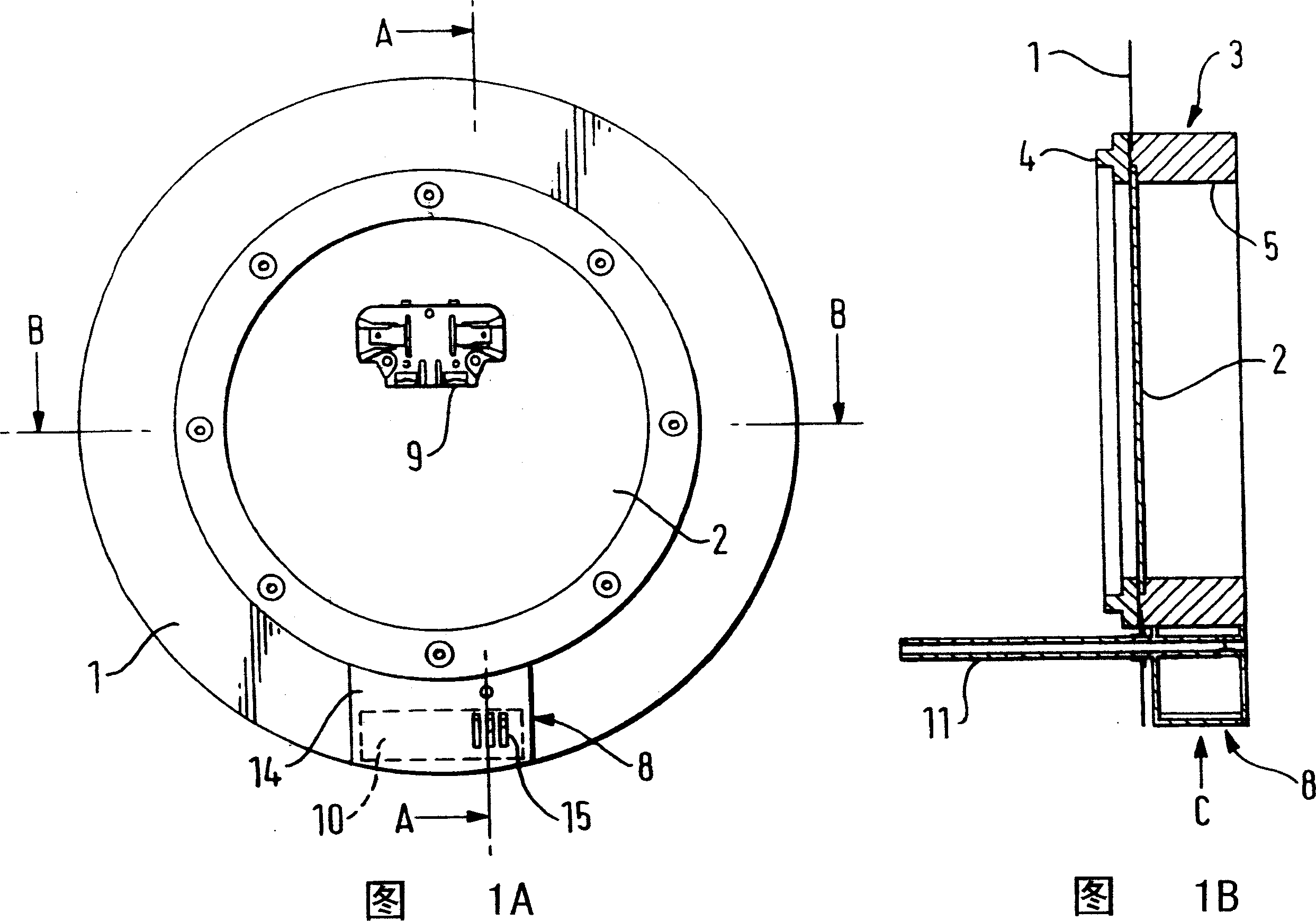
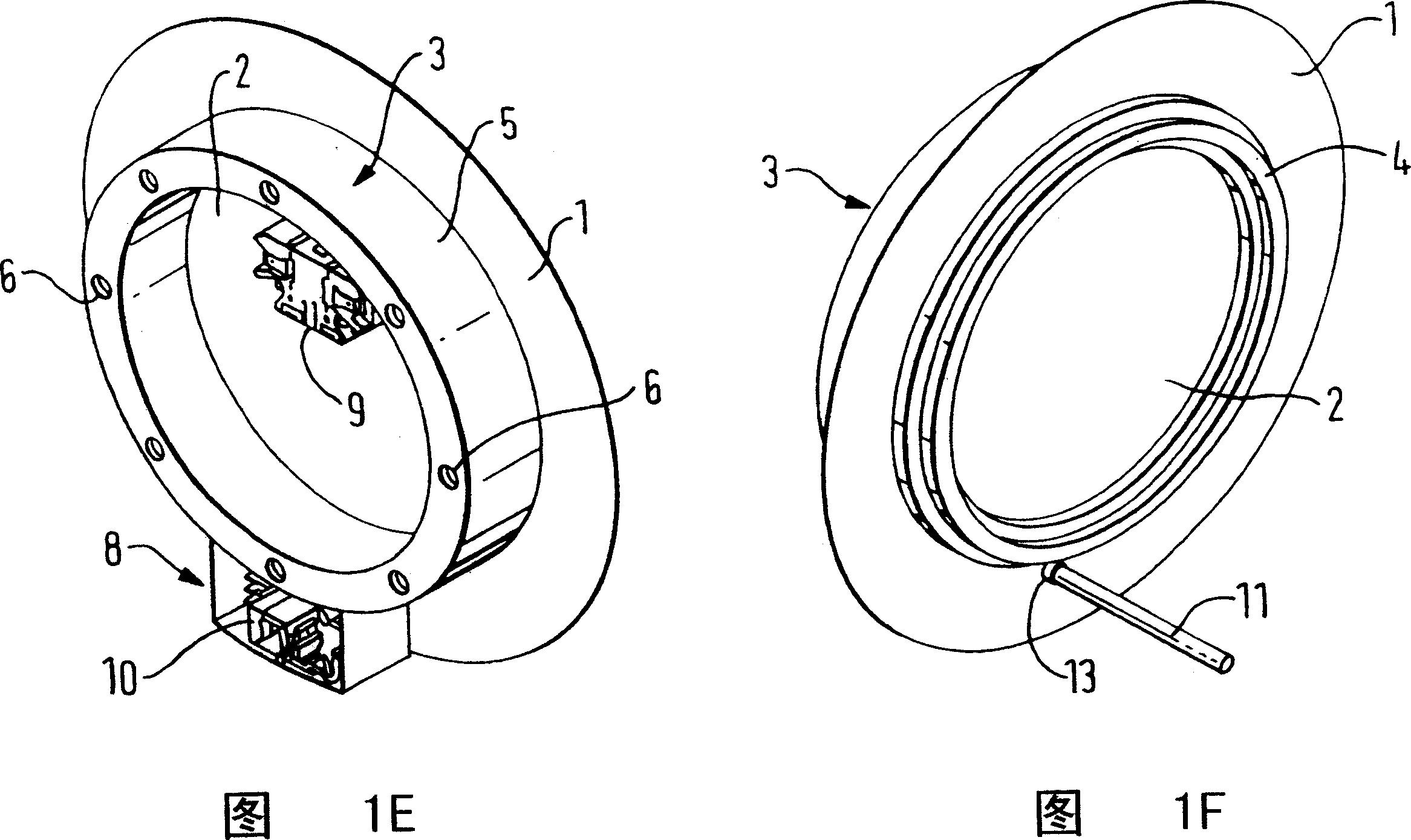
[0018] Referring first to Figures 1A to 1F, these figures show the shape of the base or bottom of an electrically heated water boiler shaped according to one embodiment of the present invention, the shape of which is only shown as part of the base or bottom wall 1 of the boiler, and should be It is understood that the rest of the boiler should be made by the device manufacturer.

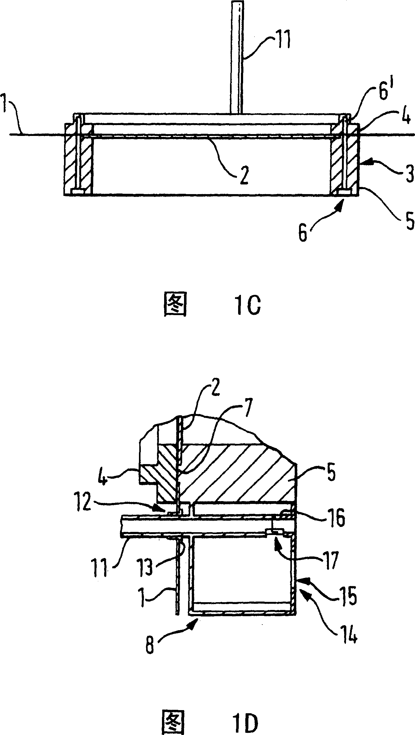
[0019] A flat electric heating element 2 is fixed in a hole formed in the bottom 1 of the boiler by means of a chassis ring 3 of molded plastic material. The chassis ring 3 is made up of two parts, a top or upper chassis ring 4 and a bottom or lower chassis ring 5, which are adapted to be screwed by self-tapping screws into aligned holes 6 and 6' formed in these two parts. fixed together. As shown in Figure 1C, the holes in the top 4 are near their innermost ends. As shown more clearly in the enlarged detailed view in Fig. 1D, the top and bottom pan rings 4 and 5 form opposing surfaces which are us...


PUM


Abstract

An electrically heated water boiling vessel incorporating a planar heating element (2) has an element protector control (9) for switching off the supply of electricity to the heating element (2) in response to a sensed element overtemperature condition and a steam sensor (10) for switching off the heating element (2) in response to the generation of steam when water is boiled in the vessel. The element protector control (9) and the steam sensor (10) are located in a bottom part of the vessel which is compartmentalized so as to segregate the potentially wetted environment of the steam sensor (10) from the element protector control (9) and thereby avoid electrical problems.

Description

technical field [0001] The present invention relates to the improvement of electric hot water boilers, such as electric kettles and hot water kettles. Background technique [0002] Electric kettles and hot water jugs etc. traditionally include submerged electric heating elements in a wire wound, mineral insulated, metal protected heating element itself secured to the element end plate which is used to attach the heating element to the On a jug, usually in a hole in the side wall of the jug. More recently, however, planar heating elements have been used, on one side of which there is a substrate which, in the form of a printed circuit or otherwise, forms a resistive circuit or layer to form a resistive heating element. The substrate may comprise, for example, a stainless steel sheet on one side which becomes an electrically insulating layer, such as glass, and the resistive heating element may be formed on this insulating layer with a further electrically insulating layer, w...

Claims


Application Information

Patent Timeline
IPC IPC(8): A47J27/21H01H37/04H05B1/02
CPCA47J27/21041A47J27/21066
Inventor R·A·奥内尔R·H·哈德菲尔德A·M·格塔
Owner OTTER CONTROLS LTD
Why Eureka
Try Eureka