Phased focusing device

A focusing device and phase control technology, applied in medical science, heating surgical instruments, ultrasonic therapy, etc.

Inactive Publication Date: 2007-03-28
何申戌
View PDF0 Cites 0 Cited by
  • Summary
  • Abstract
  • Description
  • Claims
  • Application Information

AI Technical Summary

Problems solved by technology

[0003] The purpose of the present invention is to provide a phased focusing array device with

Method used


Image

  • Phased focusing device
  • Phased focusing device

Examples


Embodiment Construction

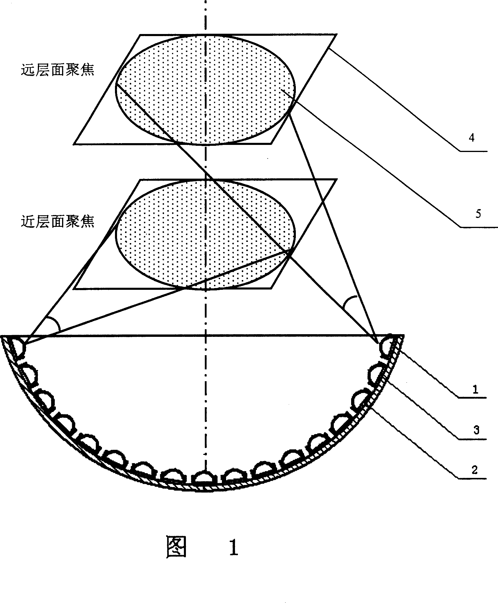
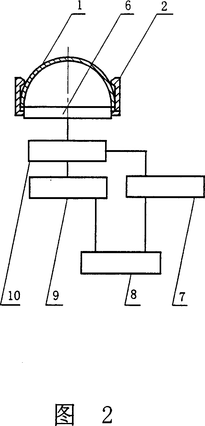
[0013] As shown in Fig. 1, the phase control focusing device of the present invention includes: a transmitter 3, and the transmitter 3 includes: at least 10 vibration elements, and the number of vibration elements depends on the superimposed value of the focused acoustic power to meet the practical application. As shown in Figure 2, each vibration element includes: base 2, piezoelectric ceramic sheet 1, frequency source 6, power device 10, power supply 8, phase shifter 7 and frequency divider 9, piezoelectric ceramic sheet 1 and frequency The source 6 is fixed on the base 2, the base 2 is fixed on the transmitter 3, the power supply 8 is connected to the input terminals of the phase shifter 7 and the frequency divider 9 respectively, and the output terminals of the phase shifter 7 and the frequency divider 9 are respectively It is connected to the input end of the power device 10, and the output end of the power device 10 is connected to the frequency source 6. The piezoelectri...


PUM

PropertyMeasurementUnit
Spherical radiusaaaaaaaaaa

Abstract

The present invention relates to a phase controlled focusing device. It includes transmitter, said transmitter includes at least 10 vibration elements, every vibration element includes base, piezoelectric ceramic piece, frequency source, power device, power supply, phase shifter and frequency divider. The piezoelectric ceramic piece and frequency source are fixed on the base, said base is fixed on the transmitter, the power supply is respectively connected with the input ends of phase shifter and frequency divider, the output ends of phase shifter and frequency divider are respectively connected with input end of power device, the output end of said power device is connected with the frequency source. Besides, said invention also provides its working principle and its extensive application field.

Description

technical field [0001] The invention relates to a phase control focusing device, in particular to a phase control focusing device with a spherical piezoelectric ceramic sheet. Background technique [0002] At present, in HIFU (High Energy Focused Ultrasound) anti-cancer hyperthermia machines, the shape of the emitter in the phase control focusing device is usually concave or a combination of concave surfaces. Although the emitter of this shape is in the direction of emission, its focus is accurate, but In the direction perpendicular to the emission direction, its focusing range is narrow, the opening angle of the planar vibration element is about 11°, and it can only produce focus within the range of ±5° from the emission direction. In order to overcome this defect, many measures have been taken. Many improvements were made, for example to increase the focus range of the emitter. People let the transmitter rotate under the drive of the motor. Although it solves the problem ...

Claims


Application Information

Patent Timeline
IPC IPC(8): B06B3/04A61N7/02A61B18/04A61B18/00
Inventor 何申戌
Owner 何申戌
Why Eureka
Try Eureka