Coupler mechanism

A buckle and tray technology, applied in the direction of record carrier structural parts, instruments, data recording, etc., can solve problems such as confusion and sound confusion

Inactive Publication Date: 2007-04-04
LITE ON IT
View PDF0 Cites 2 Cited by
  • Summary
  • Abstract
  • Description
  • Claims
  • Application Information

AI Technical Summary

Problems solved by technology

[0007] In view of the existing problem of confusion caused by the sound generated by the hook mechanism in the loading process, the purpose of the present invention is to propose a method that solves the problem of confusion caused by the two sounds generated by the hook mechanism in the film feeding process. Hook mechanism

Method used


Image

  • Coupler mechanism
  • Coupler mechanism
  • Coupler mechanism

Examples


Embodiment Construction

[0030] A hook mechanism according to a preferred embodiment of the present invention will be described below with reference to related drawings, wherein the same components will be described with the same reference symbols.

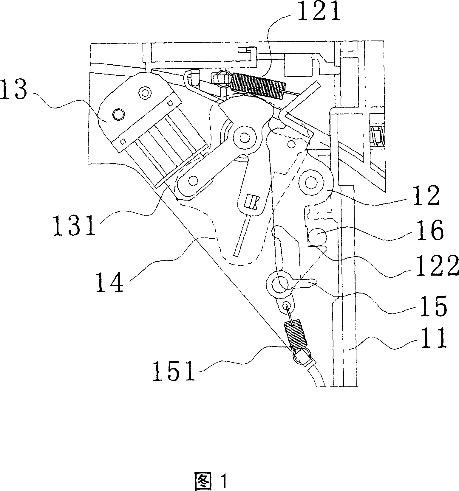
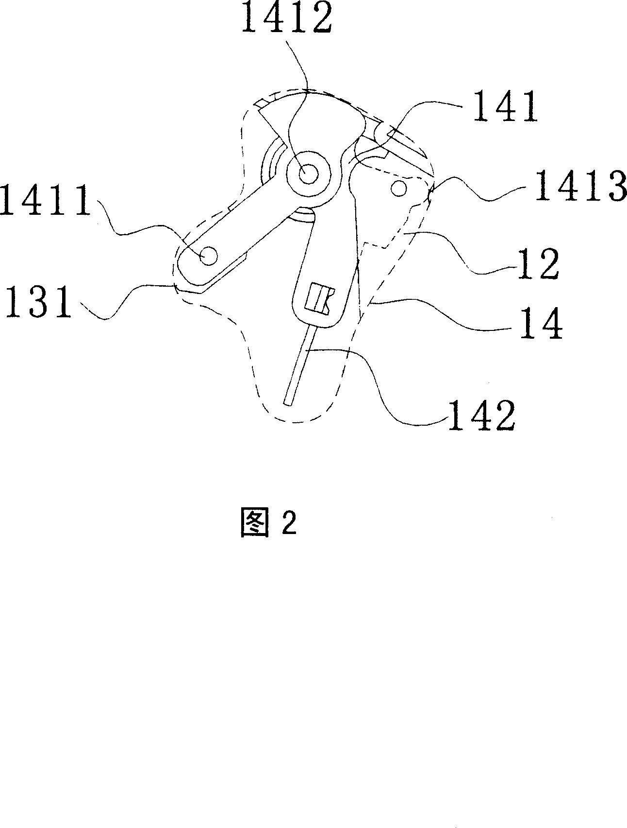
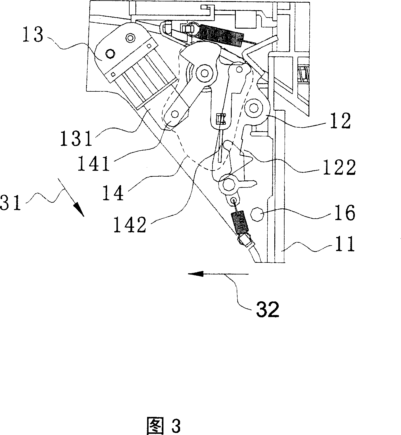
[0031] 6 to 10 are schematic diagrams of the hook mechanism and film feeding according to the first embodiment of the present invention. Referring to FIG. 6 and FIG. 7 , according to the first embodiment of the present invention, the hook mechanism at least includes a tray 11 , a hook 61 , a solenoid valve 13 , an interlocking device 14 , a first swing arm 62 and a pin 16 . Wherein, the structures of the hook 61 and the first swing arm 62 are different from the existing ones. The hook 61 is connected to the first elastic device 611 and is rotatably fixed on the tray 11 . The solenoid valve 13 is fixed on the tray 11 to provide magnetic force, and a movable block 131 is arranged on one side of the solenoid valve 13 . The linkage device 14 is connected wi...


PUM


Abstract

A hook and lock structure includes a plate, hook, electric-magnetic valve, interlock device, the first moving arm and locking pin. On the hook an extruded column is capable of rotating to fix to the plate. The electric-magnetic valve is installed on the plate and is of moving block. The interlock device is linked to the moving block and capable of rotating to fix to the plate and push the hook. The first moving arm is capable of rotating to fix to the plate to move interlock device. On the first moving arm an extruded rib leans against the extruded column to push the hook. The locking pin locks with the hook.

Description

technical field [0001] The present invention relates to a hook mechanism, in particular to a hook mechanism for optical drives. Background technique [0002] With the advancement of technology, CD-ROM drives are gradually popularized and widely used in personal computers. However, in recent years, thin CD-ROM drives have been developed, which can be used together with notebook computers, allowing users to conveniently use the slim CD-ROM drive. Read CD. And the power source of the withdrawing mechanism of the tray of the general thin CD-ROM is to utilize the so-called solenoid valve, and the solenoid valve of this form is a normally closed type. Please refer to FIG. 1 to FIG. 5 , which are schematic diagrams of the hook mechanism and film feeding and film ejection of the existing middle tray. Referring to FIG. 1 and FIG. 2 , the existing hook mechanism includes a tray 11 , a hook 12 , a solenoid valve 13 , a linkage device 14 , a first swing arm 15 and a pin 16 . Wherein,...

Claims


Application Information

Patent Timeline
Patent Type & Authority Applications(China)
IPC IPC(8): G11B33/00G11B17/04
Inventor 杨敏政陈荣福许正忠叶斯霖
Owner LITE ON IT
Why Eureka
Try Eureka