Vehicle driving assistance system

A technology for driver assistance systems, bird's eye view

Inactive Publication Date: 2007-04-25
SANYO ELECTRIC CO LTD
View PDF1 Cites 27 Cited by
  • Summary
  • Abstract
  • Description
  • Claims
  • Application Information

AI Technical Summary

Problems solved by technology

[0011] However, in this method, the driver must compare the two bird's-eye view images to grasp the state of the surroundings of the vehicle, and conversely, the driver's burden increases, which is likely to impair safety.

Method used


Image

  • Vehicle driving assistance system
  • Vehicle driving assistance system
  • Vehicle driving assistance system

Examples


Embodiment 1

[0047] (1) Explanation of the generation method of the bird's-eye view image

[0048] First, a method of generating a bird's-eye view image from a captured image captured by one camera will be described.

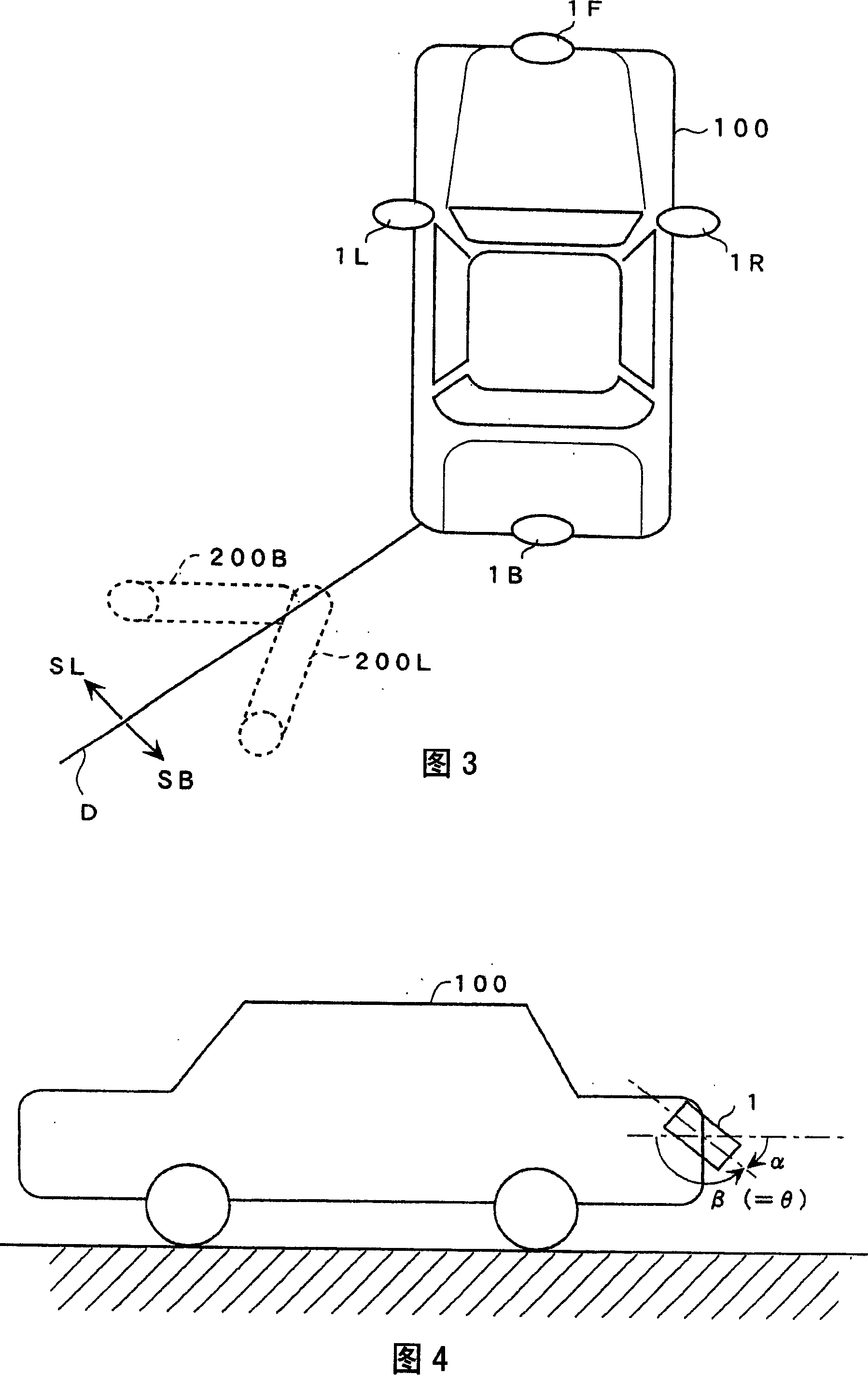
[0049] As shown in FIG. 4 , the camera 1 is disposed at the rear of the vehicle 100 obliquely downward. The angle formed by the horizontal plane and the optical axis of the camera 1 has two kinds of angles, that is, an angle represented by α and an angle represented by β in FIG. 4 . In general, α is called the angle of view or angle of depression. In this specification, the angle β is set as the inclination angle θ of the camera 1 with respect to the horizontal plane.

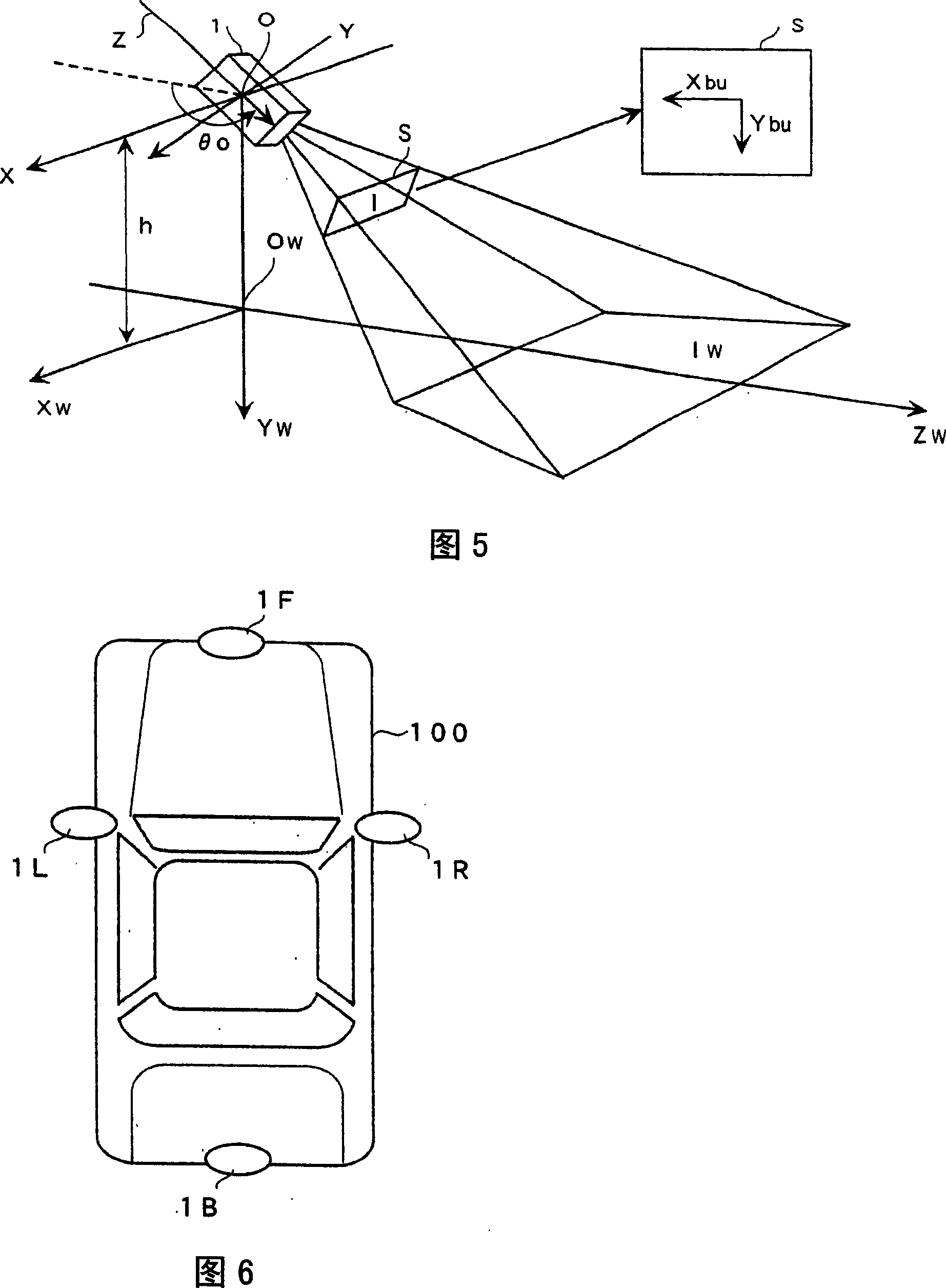
[0050] Fig. 5 shows the camera coordinate system XYZ, the coordinate system X of the imaging surface S of the camera 1 bu Y bu , and including the 2-dimensional ground coordinate system X w Z w The world coordinate system X w Y w Z w Relationship.

[0051] In the camera coordinate system XYZ, with t...

Embodiment 2

[0093] In the second embodiment, the electrical configuration of the driving assistance system is also the same as that in the first embodiment. Embodiment 2 differs from Embodiment 1 in the processing content of the image processing unit 2 .

[0094] In Embodiment 2, panoramic bird's-eye view images with priority given to both side cameras and panoramic bird's-eye view images with priority to front and rear cameras are alternately displayed on the monitor. The so-called panoramic bird's-eye view image with priority on both sides of the camera refers to the panoramic bird's-eye view coordinate system shown in Figure 9, which is obtained by using only the captured images of the left and right cameras at each overlapping portion where the two bird's-eye view images overlap. A panoramic bird's-eye view image obtained from a bird's-eye view image. Specifically, it refers to the overlapping portion 20 in Fig. 9 FL and 20 BL In the overlapping part 20 of FIG. FR and 20 BR in th...

Embodiment 3

[0110] In the above-mentioned second embodiment, the panorama bird's-eye view images prioritized by the cameras on both sides and the panoramic bird's-eye view images prioritized by the front and rear cameras are alternately displayed on the monitor. Switch between bird's-eye view images and panoramic bird's-eye view images with front and rear cameras prioritized.

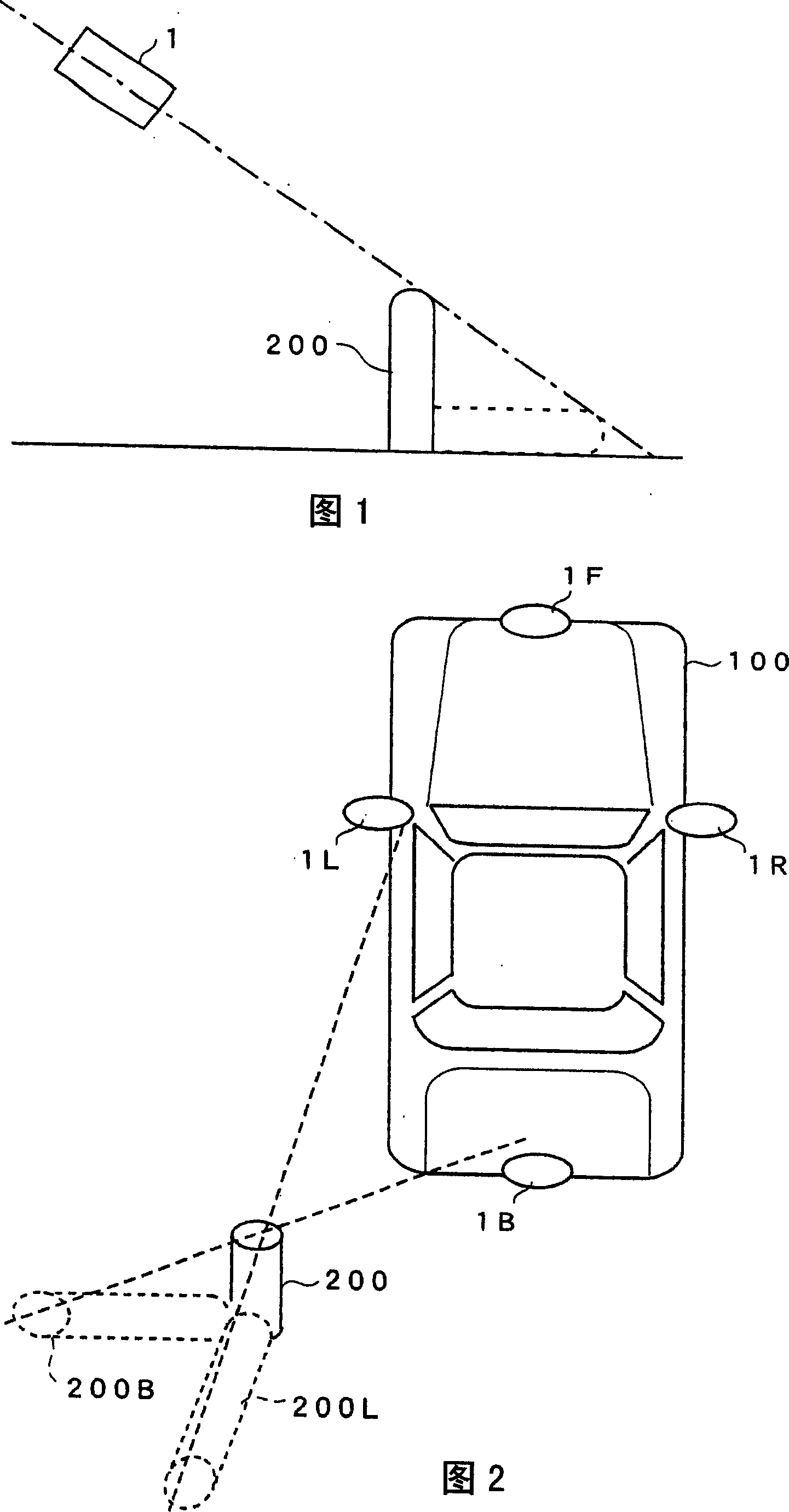
[0111] For example, as shown in FIG. 2, in the case where there is an object 200 with a height obliquely rear left from the left rear end of the vehicle, if the vehicle travels all the way to the rear, the object 200 will be missed from the imaging area of ​​the rear camera 1B. Lose. Therefore, in such a case, a panoramic bird's-eye view image in which both cameras are prioritized is generated and displayed. On the other hand, as shown in FIG. 2, in the case where there is an object 200 with height obliquely leftward from the left rear end of the vehicle, when the vehicle backs up while turning obliquely leftward,...


PUM


Abstract

A vehicle drive assistant system which converts, into birds' eye images, images photographed by a plurality of image pickup devices loaded on a vehicle and for photographing the surrounding of the vehicle, generates a synthesized bird's-eye view by synthesizing each of the obtained bird's-eye images and displays a generated synthesized bird's-eye view on a display unit, the vehicle drive assistant system comprising a means for, when each overlapping portion in which two bird's-eye views overlap each other is synthesized, setting a border line which allows two regions to be alternately disposed with respect to the overlapping portion and adopting a bird's-eye view in a region separated by the border line in the overlapping portion while adopting the other bird's-eye view in the other region separated by the border line so as to synthesize the overlapping portion.

Description

technical field [0001] The invention relates to a driving assistance system. Background technique [0002] For the driver of a car or the like, it is difficult to check the rear because of a blind spot when backing up. Therefore, a system has been developed that is equipped with an on-vehicle camera that monitors the rear of the vehicle, which is likely to be a blind spot for the driver, and displays the captured image on a screen of a car navigation system or the like. [0003] However, when a wide-angle lens is used to display a wide range, lens distortion occurs in the image. In addition, the farther away from the camera, the smaller the display is compared with a general lens, making it difficult to grasp the distance or space behind the vehicle from the captured image. [0004] Therefore, studies have been made to allow people to observe high-quality images by using image processing technology in addition to displaying images from cameras. One of the studies is to tr...

Claims


Application Information

Patent Timeline
Patent Type & Authority Applications(China)
IPC IPC(8): H04N7/28G01C11/36B60R11/04
CPCH04N7/181B60R1/00B60R2300/303B60R2300/607G06T3/4038
Inventor 杨长辉本乡仁志
Owner SANYO ELECTRIC CO LTD
Why Eureka
Try Eureka