
Drive operation tool

A working tool and working technology, applied in nailing tools, manufacturing tools, etc., can solve problems such as hindering the removal of rotating bodies

Inactive Publication Date: 2007-05-02
MAKITA CORP
View PDF1 Cites 6 Cited by
  • Summary
  • Abstract
  • Description
  • Claims
  • Application Information

AI Technical Summary

Problems solved by technology

However, when this mechanism is mounted on an electric tucking machine equipped with the above-mentioned reverse rotation preventing mechanism, it is expected that the following phenomenon will occur: when the driving of the motor is stopped, the rotation of the rotating body is prohibited by the reverse rotation preventing mechanism. When the state of reverse rotation is consistent with the state in which the rotating body is locked in the driving-in standby position by the locking unit, the rotating body, the locked portion and the locking unit are bitten into each other, and the mutual action is controlled. locked locked state
Such a phenomenon prevents the locking of the rotating body by the locking unit from being released, and may become an obstacle to a successful driving operation.

Method used


Image

  • Drive operation tool
  • Drive operation tool
  • Drive operation tool

Examples


Embodiment Construction

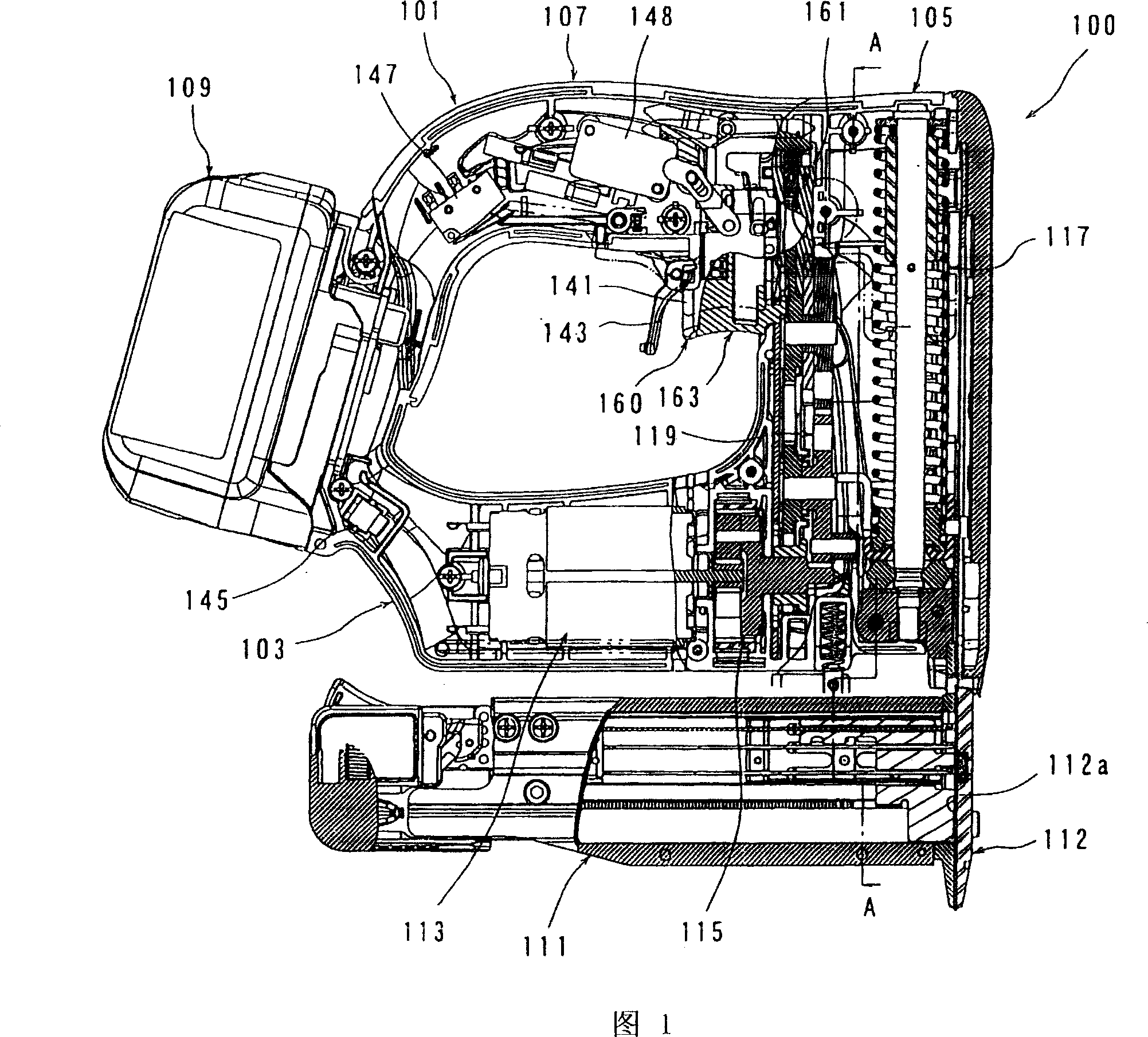
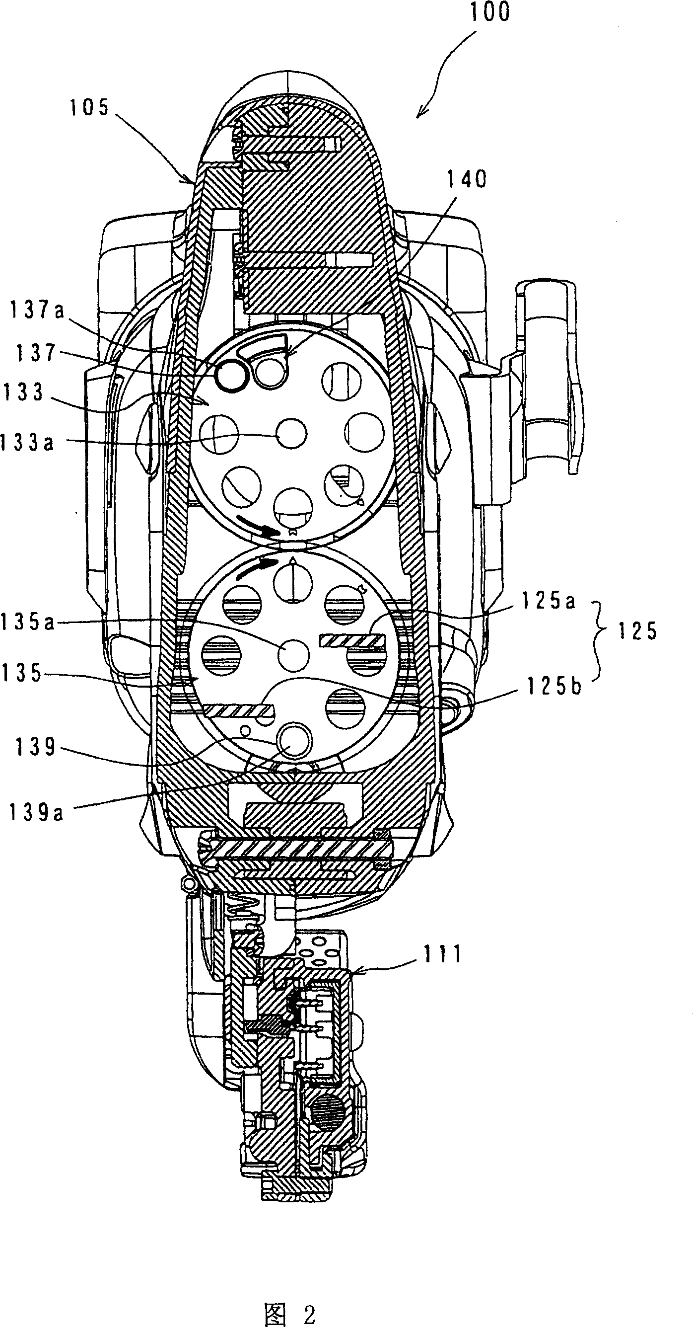
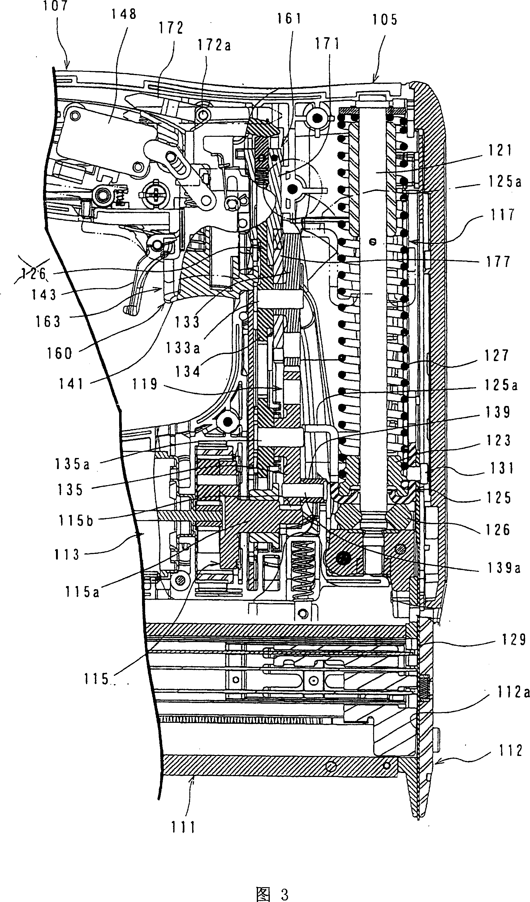
[0056] Hereinafter, an embodiment of the present invention will be described in detail with reference to FIGS. 1 to 9 . This embodiment will be described using a cordless nail gun as an example of the "driving tool" of the present invention. 1 is a side cross-sectional view showing the overall configuration of a cordless nail gun 100 according to the present embodiment, and FIG. 2 is a cross-sectional view taken along line A-A of the cordless nail gun 100 in FIG. 1 . FIG. 3 is an enlarged cross-sectional view illustrating a configuration of a main part of the cordless nail gun 100 of FIG. 1 .

[0057] As shown in FIG. 1 , regarding the rechargeable nail gun 100 involved in this embodiment, in general terms, its main body consists of: a body portion 101 forming the shell of the rechargeable nail gun 100; a battery box 109 for accommodating batteries; The staple magazine 111 is a nail as a driver that is driven into a workpiece.

[0058] The main body 101 includes: a motor hou...


PUM


Abstract

The present invention provides an effective technology for successfully carrying out the driving work for the driving work tool executing driving work of driving work piece for the material to be processed. A plug-in bolt-firing tool of the driving work tool of the present invention is so configured that: for the stop position of the driving motor, the front end(171a)of the cam block(171)is leaned against the resisting face(178d)of the cam plate(177), the converse rotating of the ratchet(116)to the arrowhead(12)direction is allowed when the cam plate(177)is blocked at the await orders position of the driving work, thereby the converse rotating of the cam plate(177)to the arrowhead(32)direction by specified amount is allowed, and a gap(179)is formed between the front end part(171a)of the cam block(171)and the resisting face(178d)of the cam plate(177).

Description

technical field [0001] The present invention relates to a driving tool for driving a workpiece into a workpiece. Background technique [0002] Conventionally, for example, the following Patent Document 1 discloses an electric tucking machine that uses an electric motor as a power source and performs driving operation of a driver such as a needle into a workpiece. The electric tucking mechanism is as follows: the hammer that hits the driven part is forced in the hitting direction by the elastic body, and the hammer is driven to the terminal position by the driving force of the motor to overcome the elastic force of the spring. In the end position, the driving force of the electric motor is cut off, so that the driving force of the elastic body strikes the driving part. In addition, the speed reduction mechanism provided on the path for transmitting the driving force of the motor to the hammer side is equipped with a reverse rotation prevention mechanism that allows the ratch...

Claims


Application Information

Patent Timeline
Patent Type & Authority Applications(China)
IPC IPC(8): B25C1/00B25C1/06
Inventor 大河内幸康
Owner MAKITA CORP
Learn More