Gas supply system for a pumping arrangement

A technology for purging gas and capillary tubes, which is applied to the components, pumps, and pump elements of pumping devices for elastic fluids, which can solve problems such as increasing costs and simplify installation.

Active Publication Date: 2007-05-02
EDWARDS LTD
View PDF0 Cites 6 Cited by
  • Summary
  • Abstract
  • Description
  • Claims
  • Application Information

AI Technical Summary

Problems solved by technology

These connections may undesirably transfer vibrations from the pumping unit to the gas supply system
In addition, the system is often equipped with different sets of connecting tubing to enable the system to be connected to a range of different pumping mechanisms, which can add significantly to the cost

Method used


Image

  • Gas supply system for a pumping arrangement
  • Gas supply system for a pumping arrangement
  • Gas supply system for a pumping arrangement

Examples


Embodiment Construction

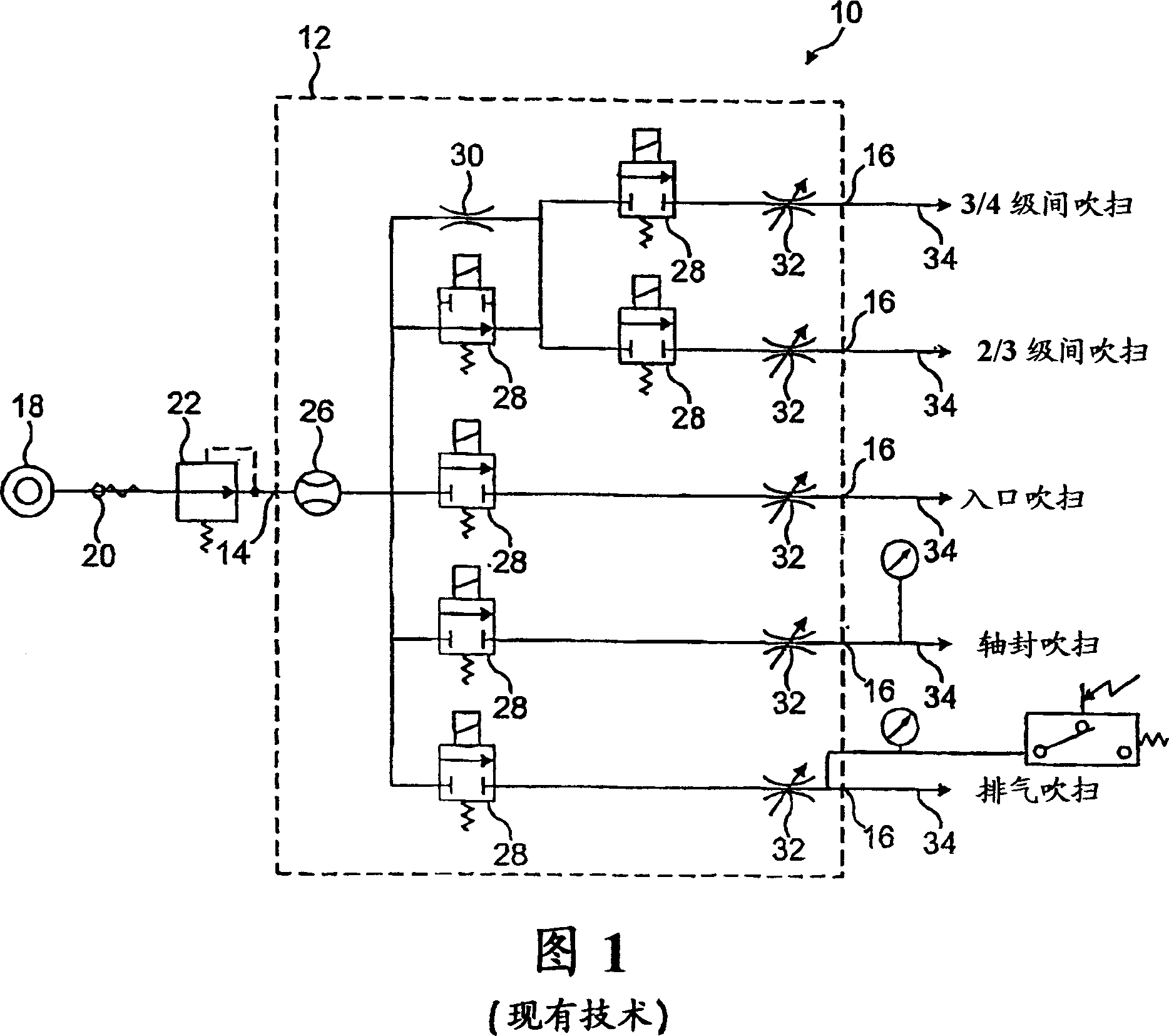
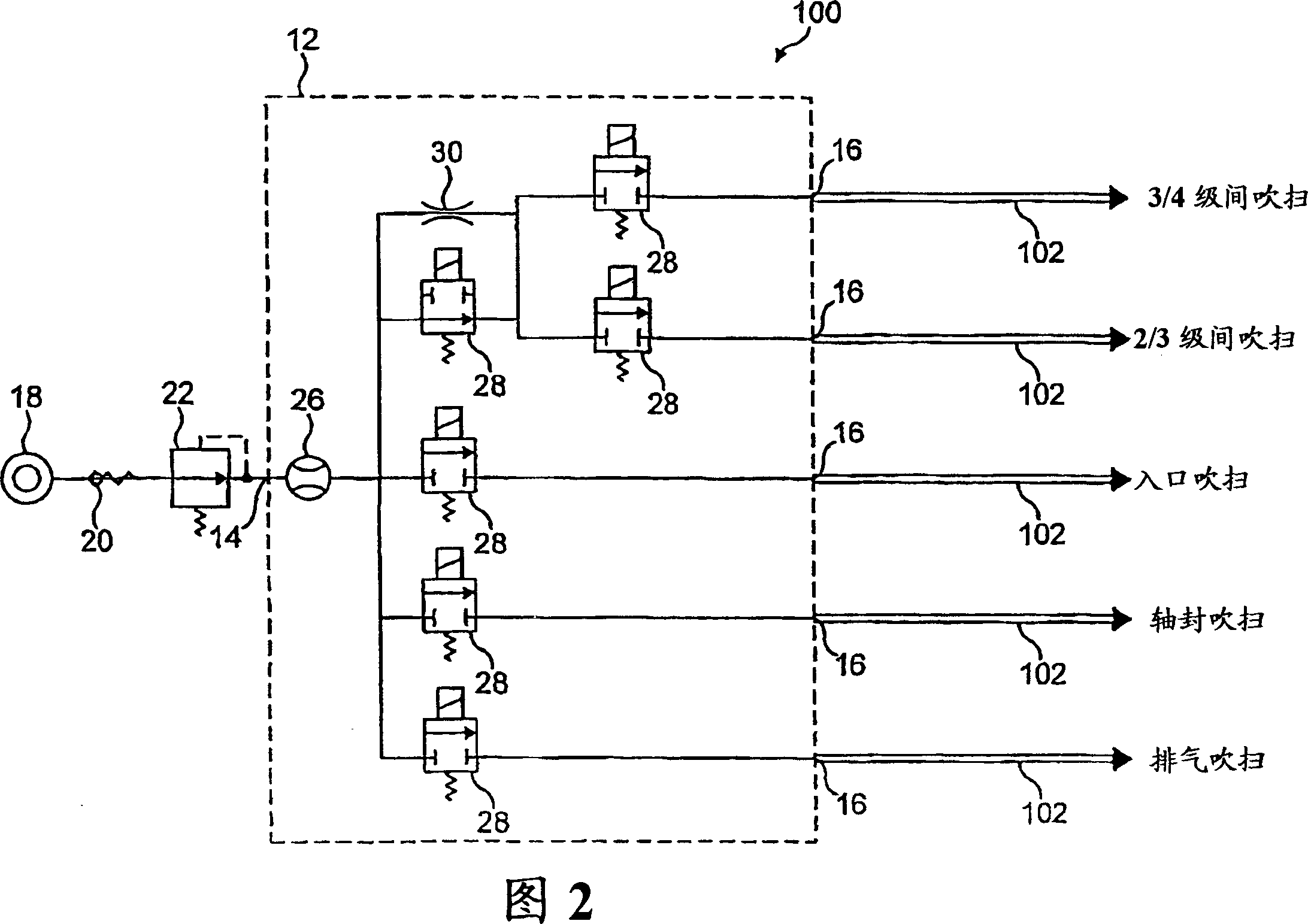
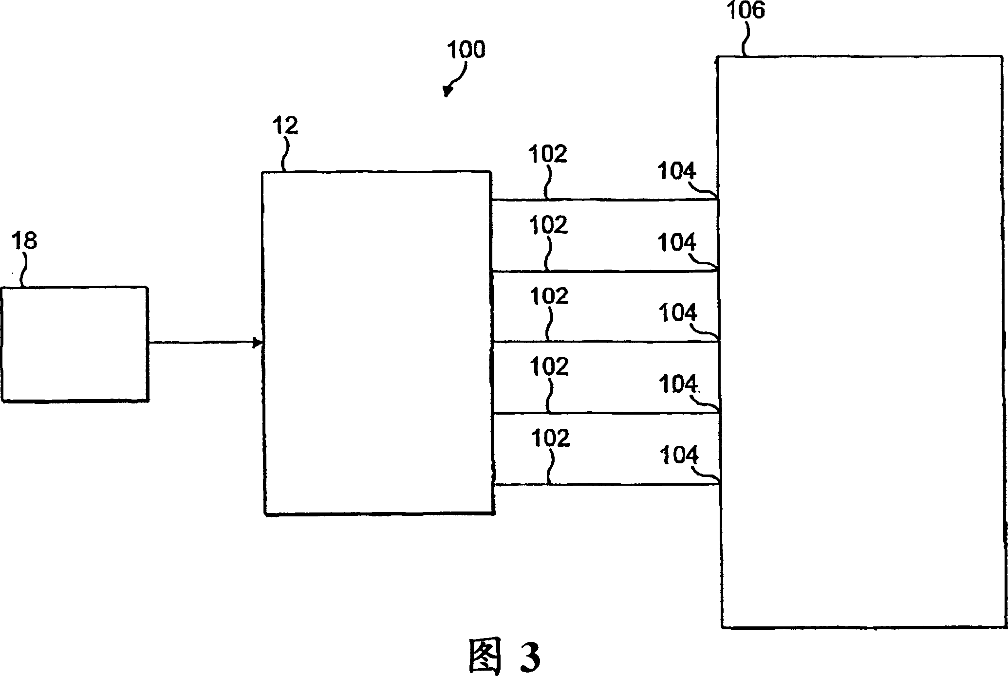
[0021] The gas supply system 100 of the embodiment shown in FIG. 2 differs from the known system previously described with reference to FIG. 1 in that a fixed flow restrictor 30 and The variable restrictor 32 is eliminated, and the rigid tube 34 is replaced by a flexible capillary 102 . As shown in FIG. 3 , each capillary 102 is connected to a corresponding purge port 104 of a pumping device 106 . As shown in Figure 2, these ports 104 may be located at various locations, for example near the inlet, exhaust, shaft seal, and / or at various locations between the suction stages of the pumping arrangement.

[0022] The inner diameter and length of capillary 102 determine the flow rate of purge gas to the purge port. The delivery system 100 may be equipped with a plurality of capillaries 102 of different diameters (eg, ranging from 1 mm to 5 mm). This may enable the user to select an appropriate diameter capillary 102 for connection to a particular purge port, where the capillary m...


PUM


Abstract

A system (100) for supplying an inert purge gas to a pumping arrangement (106) includes a plurality of flexible capillary tubes (102) each for conveying the gas from a respective outlet of a manifold (12) to a respective port (104) of the pumping arrangement (106). The internal diameter and length of each tube (102) control the gas flow rate to the respective port (104).

Description

technical field [0001] The present invention relates to a system for supplying an inert purge gas to a pumping arrangement. Background technique [0002] Vacuum pumping arrangements for pumping liquids from semiconductor tools typically employ multi-stage positive displacement pumps utilizing intermeshing rotors as backing pumps. The rotors in the stages may have the same type of profile, or the profiles of the stages may be different. [0003] During semiconductor processing, such as a chemical vapor deposition process, deposition gases are supplied to a process chamber to form a deposited layer on a substrate surface. Due to the short residence time of the deposition gas chamber, only a small fraction of the gas supplied to the process chamber is consumed during the deposition process. Therefore, unconsumed gas molecules drawn from the process chamber by the vacuum pump may pass through the gas pump in a highly reactive state. Accordingly, gas pump components may be sus...

Claims


Application Information

Patent Timeline
Patent Type & Authority Applications(China)
IPC IPC(8): F04B53/00C23C16/44F04B53/06F04D19/04
CPCF04B53/06F04D19/042C23C16/4412F04D19/046Y10T137/0324Y10T137/0419Y10T137/8593Y10T137/87877F04B53/00C23C16/44
Inventor P·诺尔思D·P·曼森
Owner EDWARDS LTD
Why Eureka
Try Eureka