Method for controlling content of salt and alkali in basin tidal flat

A tidal flat and watershed technology, applied in construction, application, soil drainage, etc., can solve problems such as shallow depth, easy silting, collapse, and salinity drainage effect

Inactive Publication Date: 2007-05-16
宋建中
View PDF0 Cites 14 Cited by
  • Summary
  • Abstract
  • Description
  • Claims
  • Application Information

AI Technical Summary

Benefits of technology

The technical feature described by this inventor relates to an improved method that uses a special type called meshed pipes placed underground during flooding or other conditions where there may occur high levels of moisture content such as sea waves or snowmelt. This allows these materials to enter the pipeline without getting stuck up due to gravity or pressure on its way downstream. By controlling the depth at which it enters the system, the amount of material entering the pipeline will also vary depending upon factors like temperature and humidity. Overall, this innovative design improves the efficiency and accuracy of removing unwanted substances while minimizing damage caused by excessive pressures applied thereto.

Problems solved by technology

The technical problem addressed by this patented technology relates to improving the ability for farmers to produce food on these areas while reducing water usage during periods when there may be heavy rain or snowfall.

Method used


Image

  • Method for controlling content of salt and alkali in basin tidal flat
  • Method for controlling content of salt and alkali in basin tidal flat

Examples


Embodiment 1

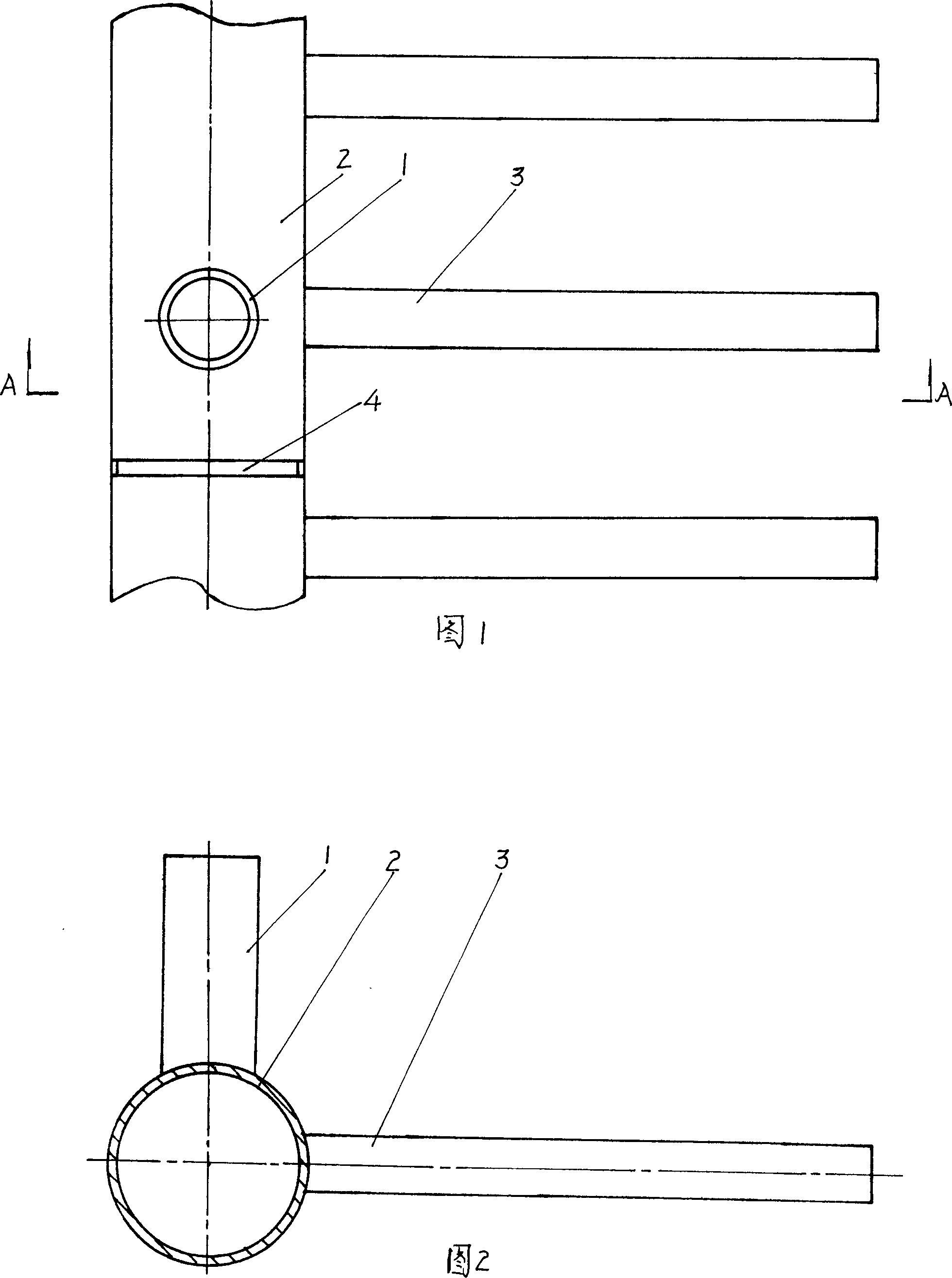
[0017] As shown in Fig. 1, Fig. 2 and Fig. 3, the method for controlling river basin tidal flat saline-alkali in the present embodiment, it comprises the following steps:

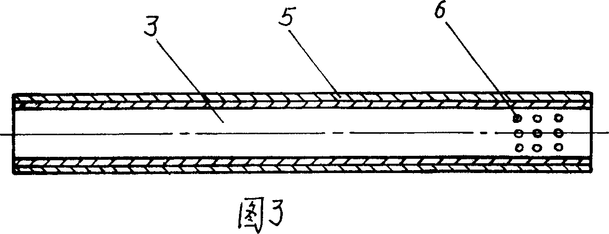
[0018] A, at first on the hollow branch pipe 3 that the diameter that PVC plastic is made is 2cm, process out some rows of sieve holes 6 that the diameter is 1mm, and the distance between every row of sieve holes 6 is 1cm;

[0019] B, wrapping 2 layers of mesh bags 5 on the outer surface of the hollow branch pipe 3 processed through the sieve holes;

[0020] c, burying a main pipeline 2 with a diameter of 1m in the tidal flats of the watershed, and its depth is 1.7m;

[0021] d. In the tidal flats of the watershed, dig a channel with a depth of 1.5m to bury the hollow branch pipe 3 every 5-10m, then put the hollow branch pipe 3 and lay 4mm thick fine sand around the hollow branch pipe 3 to wrap the hollow branch pipe 3 live, one end of each hollow branch pipe 3 is connected with the main pipe 2, and the ot...

Embodiment 2

[0024] As shown in Fig. 1, Fig. 2 and Fig. 3, the method for controlling river basin tidal flat saline-alkali in the present embodiment, it comprises the following steps:

[0025] A, at first on the hollow branch pipe 3 that the diameter that PVC plastic is made is 5cm, process out some row diameters and be the sieve holes 6 of 5mm, the distance between every row of sieve holes 6 is 2cm;

[0026] B, winding 3 layers of mesh bags 5 on the outer surface of the hollow branch pipe 3 with the sieve holes processed;

[0027] c. Embedding a main pipeline 2 with a diameter of 1.5m in the tidal flats of the river basin and a depth of 2.2m;

[0028] d. In the tidal flats of the river basin, dig a channel with a depth of 2.0m to bury the hollow branch pipe 3 every 5-10m, then put the hollow branch pipe 3 and lay 4mm thick fine sand around the hollow branch pipe 3 to wrap the hollow branch pipe 3 live, one end of each hollow branch pipe 3 is connected with the main pipe 2, and the other ...

Embodiment 3

[0031] As shown in Fig. 1, Fig. 2 and Fig. 3, the method for controlling river basin tidal flat saline-alkali in the present embodiment, it comprises the following steps:

[0032] A, at first on the hollow branch pipe 3 that the diameter that PVC plastic is made is 4cm, process out some row diameters and be the sieve holes 6 of 3mm, the distance between every row of sieve holes 6 is 1.5cm;

[0033] B, wrap 3 layers of mesh bags 5 on the outer surface of the hollow branch pipe 3 with the sieve holes processed;

[0034] c, burying the main pipeline 2 with a diameter of 1.3m in the tidal flats of the watershed, and its depth is 1.9m;

[0035] d. In the tidal flats of the river basin, dig a channel with a depth of 1.7m to bury the hollow branch pipe 3 every 5-10m, then put the hollow branch pipe 3 and lay 4mm thick fine sand around the hollow branch pipe 3 to wrap the hollow branch pipe 3 live, one end of each hollow branch pipe 3 is connected with the main pipe 2, and the other ...


PUM


Abstract

The invention involves a method of disposing the alkali of drain basin beach and belongs to a three-dimensional disposing method using the laying pipe to discharging alkali and salt. The invention mainly resolves the technical difficulties of depth shallow, easy to choking and caving-in collapse, the effects of discharging alkali and salt poor in the prior method.The technical schemes used in the invention are: a disposing the alkali of drain basin beach method includes the following steps : a. machining sieve meshes on the hollow tubes firstly; b. binding net bags on the surface of hollow tubes machined sieve meshes; c. burying main pipes in the drain basin beach lands, the depth is 1.7-2.2m; d. digging a canal to burying the hollow tubes every 5~10m in the drain basin beach lands, then putting hollow tubes in and laying fine sands around the hollow tubes to packing the hollow tubes, one end of every hollow tubes are linked with main pipes; e. equipping vertical tubes and sluice valves which can control the water level on the main pipes in order to controlling the water level in the suitable area for plant growth.

Description


Claims


Application Information

Patent Timeline
Owner 宋建中
Why Eureka
Try Eureka