Device for placing an object

A technology of objects and actuators, which is applied in the direction of metal processing machinery parts, large fixed members, metal processing equipment, etc., can solve the problems of unstable movement of objects, aggravation, and affecting the positioning accuracy of objects, so as to achieve simple alternate contact and solve placement problems Effect

Inactive Publication Date: 2007-05-16
SIEMENS AG
View PDF6 Cites 1 Cited by
  • Summary
  • Abstract
  • Description
  • Claims
  • Application Information

AI Technical Summary

Problems solved by technology

When the object is processed, this will cause the movement of the object to be unstable and poorly guided, thereby affecting the processing quality of the object
Constantly changing friction conditions, determined eg by the curvature of the brush 3, also affect the positioning accuracy of the object
During the processing, once the object moves in the opposite direction or its moving direction changes, the above problems will be further aggravated

Method used


Image

  • Device for placing an object
  • Device for placing an object
  • Device for placing an object

Examples


Embodiment Construction

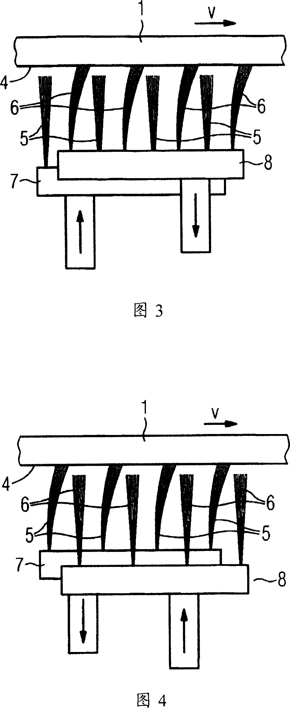
[0027] Figures 3 and 4 show a first embodiment of the device according to the invention. In the described embodiment, an object in the form of a sheet metal 1 is placed on the brush. A first part 5 of the brush is connected to a die 7 . A second part 6 of the brush is connected to a mold 8 . By alternately raising and lowering the first part 5 of the brush and the second part 6 of the brush, these two parts of the brush alternately remain in contact with one surface 4 of the sheet metal. In the first embodiment shown in Fig. 3 and Fig. 4, the alternate ascending and descending of the first part 5 of the brush and the second part 6 of the brush are realized by the alternate ascending and descending of the relatively movable molds 7 and 8. At the point in time shown in FIG. 3 , the first part 5 of the brush is not in contact with the surface of the metal sheet and the second part 6 of the brush remains in contact with the surface of the metal sheet 1 . That is, at the point i...


PUM


Abstract

The invention relates to a device (10) which is used to place an object (1). The object (1) is placed on brushes (5,6), whereby a first part of the brushes (5) are in contact with the surface (4) of the object (1) and alternatively with a second part of the brushes (6). The invention also relates to a device (10) which is used to place an object (1) placed on brushes (5,6) enabling the object to (1) be positioned in a precise manner.

Description

technical field [0001] The invention relates to a device for mounting an object, wherein said object is mounted on a brush, a first portion and a second portion of said brush being alternately kept in contact with a surface of said object. Background technique [0002] Various methods of positioning objects are known in machines for processing objects such as sheet metal, such as machine tools, special machine tools or robotic devices. A common placement method is to place the item on a brush. [0003] What Fig. 1 shows is exactly such a kind of customary method of placing an object, and the object shown in Fig. 1 is a metal thin plate 1 for example. In this case, the sheet metal 1 is conventionally placed on a brush 3 connected to a stand 2 . The brush is in contact with one surface 4 of the metal sheet 1 . Due to the contact between the metal sheet 1 and the surface 4 of the object 1, a sticking occurs when the metal sheet 1 is moved at a moving velocity v by a drive me...

Claims


Application Information

Patent Timeline
Patent Type & Authority Applications(China)
IPC IPC(8): B23Q1/03
CPCB23Q1/032
Inventor 尤维·莱德拉迪特马·斯托伊伯
Owner SIEMENS AG
Why Eureka
Try Eureka