Electric cylinder erecting system loading and performance testing device and testing method

A system loading and testing device technology, applied in measurement devices, electrical testing/monitoring, machine/structural component testing, etc., can solve the problems of inability to multi-cylinder synchronous drive reasoning and control performance testing, and achieve convenient and safe operation. Effect

Active Publication Date: 2019-01-08
BEIJING MECHANICAL EQUIP INST
View PDF8 Cites 0 Cited by
  • Summary
  • Abstract
  • Description
  • Claims
  • Application Information

AI Technical Summary

Problems solved by technology

[0005] In view of the above analysis, the present invention aims to provide an electric cylinder erecting system loading and performance testing device and testing method, which sol

Method used


Image

  • Electric cylinder erecting system loading and performance testing device and testing method
  • Electric cylinder erecting system loading and performance testing device and testing method

Examples


Example Embodiment

[0032] Example 1

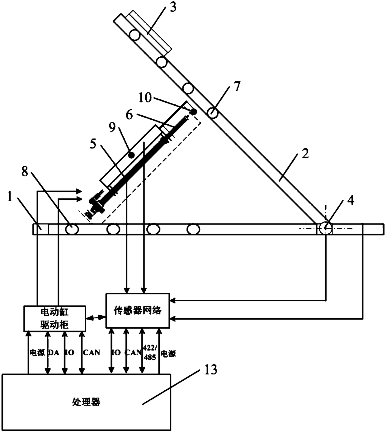
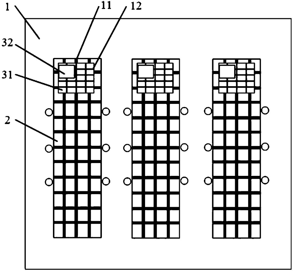
[0033] This embodiment provides a loading and performance testing device for an electric cylinder erection system, such as Figure 1 to Figure 2 As shown, it includes a processor 13 (not shown in the figure), a base 1 and multiple sets of test benches located on the base 1. The structure, shape and size of the multiple sets of test benches are the same, and the above-mentioned test benches include brackets 2, The movable load 3 on the bracket 2, a plurality of upper fulcrums 7 slidably connected with the bracket 2, and a plurality of lower fulcrums 8 slidably connected with the base 1, the adjacent brackets 2 are detachably and fixedly connected; one end of the bracket 2 is connected to the base. The seat 1 is connected in rotation, and the other end is suspended in the air. The connection between the bracket 2 and the base 1 is provided with an angular displacement sensor 4, and the angular displacement sensor 4 is connected with the processor 13; when in u...

Example Embodiment

[0053] Embodiment 2

[0054] This embodiment provides a method for testing the loading and performance of an electric cylinder erecting system, using the device for testing the loading and performance of an electric cylinder erecting system provided by the embodiment, and the above test method includes a single electric cylinder motion accuracy test, a multi-electric cylinder synchronous motion Accuracy testing, gravity loading control of electric cylinders, and active loading control of electric cylinders.

[0055] Specifically, the above-mentioned single electric cylinder motion accuracy test includes the following steps: disassembling one of the electric cylinders from the other electric cylinders as a test cylinder; starting the test cylinder, the end of the piston rod of the test cylinder extends outward, and the support is lifted , the angular displacement sensor collects the actual rotation angle of the bracket, according to the theoretical elongation value of the pisto...


PUM


Abstract

The invention discloses an electric cylinder erecting system loading and performance testing device and a testing method and belongs to the technical field of erecting of electric cylinders, which solves the problem that the existing electric cylinder loading and testing device cannot test the inference and control performance of multi-cylinder synchronous driving. The device comprises a processor, a base and a plurality of sets of test stands located on the base; the test stand comprises a support, a movable load located on the support, a plurality of upper support points slidably connected with the support, and a plurality of lower support points slidably connected with the base; the adjacent supports are detachably and fixedly connected; one end of the support is rotationally connectedwith the base, and the other end is suspended; an angular displacement sensor is arranged at the joint of the support and the base; and the angular displacement sensor is connected with the processor.The method comprises single electric cylinder motion accuracy test, multi-electric cylinder synchronous motion accuracy test, gravity loading control of the electric cylinder and active loading control of the electric cylinder. The above device and method can be used for electric cylinder erecting system loading and performance testing.

Description

technical field [0001] The invention relates to an electric cylinder erecting technology, in particular to an electric cylinder erecting system loading and performance testing device and testing method. Background technique [0002] Electric cylinders are directly driven by motors. Compared with hydraulic cylinders, they have the advantages of clean energy, simple system composition, high control precision and good dynamic characteristics. They are widely used in small and medium power drive mechanisms. However, for larger loads, in order to reduce the thrust of a single electric cylinder while balancing the thrust and preventing rollover, it is usually necessary to use dual-cylinder drive or multi-cylinder synchronous drive. [0003] In the initial stage of system design, in order to quickly verify the control strategy, the test device is required to automatically complete the system loading test and test the control performance of the dual-cylinder drive or multi-cylinder ...

Claims


Application Information

Patent Timeline
IPC IPC(8): G01M99/00G05B23/02
CPCG01M99/007G05B23/02
Inventor 李方俊王利崔臣君李俊峰王生捷
Owner BEIJING MECHANICAL EQUIP INST
Why Eureka
Try Eureka