
Loading and unloading device and method for load test of large structural member

A large-scale structure, load test technology, applied in the testing of machine/structural components, measuring devices, testing of mechanical components, etc., can solve the problems of time-consuming and laborious unloading, complicated unloading process, huge reaction force anchoring device, etc. The unloading operation is simple and convenient, the risk factor is reduced, and the operation is convenient and safe.

Active Publication Date: 2020-07-28
HUBEI IND CONSTR GRP +1
View PDF6 Cites 0 Cited by
  • Summary
  • Abstract
  • Description
  • Claims
  • Application Information

AI Technical Summary

Problems solved by technology

Large-span beam and slab load tests have a very large loading tonnage, and conventional single-beam (slab) vertical loading methods require huge counter force anchoring devices, resulting in high costs, especially for prototype tests.
Moreover, there are often many loading points in the test (multiple loading points generally refer to more than 5 loading sections on a single beam (slab)), and the single point force is huge (such as hundreds of tons), requiring a large number of pulling machines, which further increases the cost
[0004] Moreover, the unloading process of the long-span beam-slab load test is often more complicated. Generally, a single tie rod cannot be released directly, otherwise the load on the adjacent tie rods may increase, and in severe cases, the tie rods may be overloaded. Level unloading, unloading is more time-consuming and laborious than loading
Theoretically, if each loading point has a loading jack, the problem of loading and unloading can be solved, but as many as dozens of large-tonnage loading equipment are required, and the cost is extremely high

Method used


Image

  • Loading and unloading device and method for load test of large structural member
  • Loading and unloading device and method for load test of large structural member
  • Loading and unloading device and method for load test of large structural member

Examples


Embodiment Construction

[0037] In order to make the purpose, technical solutions and advantages of the embodiments of the present invention clearer, the technical solutions in the embodiments of the present invention will be clearly and completely described below in conjunction with the drawings in the embodiments of the present invention. Obviously, the described embodiments It is a part of embodiments of the present invention, but not all embodiments. It should be understood that the specific embodiments described here are only used to explain the present invention, not to limit the present invention. Based on the embodiments of the present invention, all other embodiments obtained by persons of ordinary skill in the art without making creative efforts belong to the protection scope of the present invention.

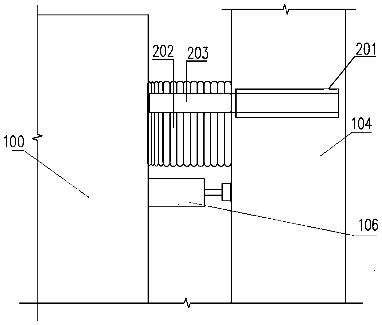
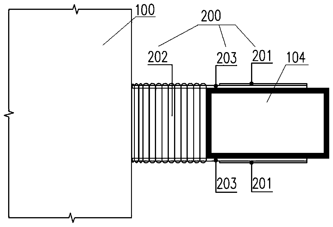
[0038] Such as figure 1 , figure 2 As shown, a grading loading and unloading mechanism includes a distribution beam 104, a jack 106 and a grading loading and unloading assembly 200; wherei...


PUM


Abstract

The invention discloses a loading and unloading device for a load test of a large structural member. A graded loading and unloading mechanism is mounted at a loading end; when a certain loading pointis loaded or unloaded, the jack only needs to be installed between the distributive girder of the loading point and the large structural member, a gap is formed between the distributive girder and thelarge structural member through extension of the jack, and accurate loading or unloading is achieved by controlling the total thickness of the inserted or taken-out base plate. Correspondingly, the invention further discloses a loading and unloading method for the load test of the large structural member. The loading and unloading device is adopted, the loading step and the unloading step are carried out in multiple rounds, graded loading and graded unloading are achieved, when loading or unloading is carried out on a certain loading point, due to the fact that the single-time force application is small, too large loads cannot be added to the adjacent pull rods, the safety of the pull rods can be guaranteed, anchor retreating and unloading operation is easy and convenient, and the workingefficiency is greatly improved.

Description

technical field [0001] The invention relates to a load test device, in particular to a loading and unloading device and method for the load test of large structural members. Background technique [0002] Load test is a technical activity in the field of engineering to test the reliability of important large structural components (generally referring to components with a length greater than 30m). The load test has high technical requirements, complicated process, and high risks to personnel and equipment, so it must be operated in strict accordance with reliable procedures. [0003] For important large-scale structural components, such as long-span beams and slabs, the common method of load test is symmetrical lateral placement, symmetrical self-anchor loading, and according to the number of loading points, multiple tie rods are used to apply and lock the loading force. The process is generally applied in stages according to the set procedure. The large-span beam-slab load ...

Claims


Application Information

Patent Timeline
IPC IPC(8): G01M13/00
CPCG01M13/00
Inventor 俞栋华刘争吴金池彭自强李毅宋彦波周俊
Owner HUBEI IND CONSTR GRP
Learn More