Connecting port structure of subway station and property development and rail transit subway platform

A technology of subway station and interface structure, applied in the field of underground space, can solve the problems of coordination difficulties, pipeline blocking, encroaching on the interface width, etc., and achieve the effect of stable and reliable interface structure, reducing disturbance, and reducing disturbance.

Pending Publication Date: 2020-07-03
CHINA RAILWAY SIYUAN SURVEY & DESIGN GRP
View PDF0 Cites 1 Cited by
  • Summary
  • Abstract
  • Description
  • Claims
  • Application Information

AI Technical Summary

Problems solved by technology

However, there will be some problems in the above-mentioned measures, such as ① re-build the inverted "U"-shaped beam-column system in the frame to support and strengthen the interface. Satisfy the evacuation width or block the pipeline, and the coordination is difficult, time-consuming and laborious; ②The roof of the subway station at the interface is removed, the steel bars are retained, and the frame beams are rebuilt. This method has a large amount of work and has a great impact on the station. Covering soil, blocking traffic, usually does not meet the construction conditions; ③ planting bars on the roof of the station and pouring frame beams, this method also needs to unload the covering soil above the roof, and because the new beam body and the existing frame structure are only connected by planting bars , the mechanical performance is difficult to be guaranteed, and there are still major safety hazards. Therefore, on the basis of safety and reliability and not affecting the building function, it is impossible to solve the problem of interface reconstruction between the station and property development with a small cost and a small disturbance to the station. Stress problem

Method used


Image

  • Connecting port structure of subway station and property development and rail transit subway platform
  • Connecting port structure of subway station and property development and rail transit subway platform
  • Connecting port structure of subway station and property development and rail transit subway platform

Examples


specific Embodiment

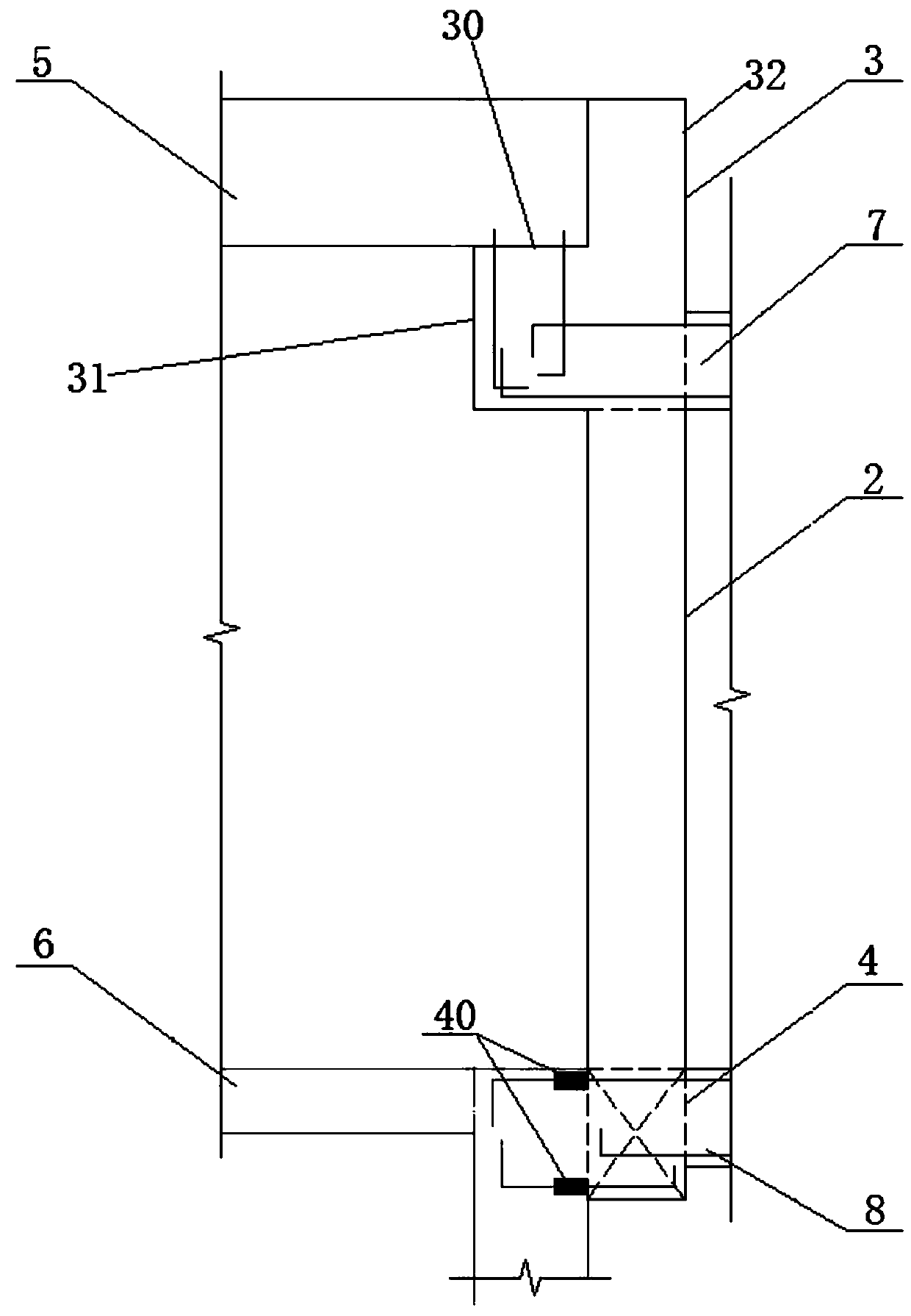
[0026] To optimize the above scheme, see figure 2 , Figure 5 and Figure 6 , the shelving beam is an L-shaped beam 3, the horizontal section 31 of the L-shaped beam 3 is located on the top of the two interface columns 2, and the upper surface of the horizontal section 31 of the L-shaped beam 3 is for the shelving The laying surface 30 of the station roof 5 and the location for the access of the property development roof 7 are located at the horizontal section 31 of the L-shaped beam 3 . In this embodiment, in order not to occupy the frame width of the existing entrance and exit of the station and reduce the occupation of space, the above-mentioned shelving beam can be designed as an L-shaped beam 3. For the convenience of description, the L-shaped beam 3 is defined as two parts, respectively It is a horizontal section 31 and a vertical section 32, wherein the shelving surface 30 is on the upper surface of the horizontal section 31, and the horizontal section 31 is a protru...


PUM


Abstract

The invention relates to a connecting port structure of a subway station and property development, and further relates to a rail transit subway platform. The connecting port structure includes a placement beam for placing a station top plate, two connecting port columns which can be connected with existing frame columns and a connecting port bottom beam which can be connected with a station mediumplate, the placement beam is located at the tops of the two connecting port columns, both connecting port columns are located on the connecting port bottom beam, the placement beam is provided with aplacement position for a property development top plate to be connected in, and the connecting port bottom beam is provided with an installation position for a property development bottom plate to beconnected in. The rail transit subway platform includes the existing frame columns, the station top plate, the station medium plate, the property development top plate, the property development bottom plate and the connecting port structure of the subway station and the property development. According to the connecting port structure of the subway station and the property development and the railtransit subway platform, the problem of the placement of the station top plate and the station medium plate in a subway station as well as the property development top plate and the property development bottom plate in the property development is solved through the matching of the placement beam, the connecting port columns and the connecting port bottom beam.

Description

technical field [0001] The invention relates to the technical field of underground space, in particular to an interface structure between a subway station and property development and a rail transit subway platform. Background technique [0002] In order to realize the comprehensive benefits of subway operation, property development is usually carried out around the subway station and connected to the station hall level. However, because the planning and construction speed of property development projects is later than that of the station, and the property development project cannot be given enough attention during the construction of the station, there are cases where the interface is not reserved in advance or the interface is difficult to meet the force requirements, and the interface needs to be modified. In order to meet the building function and structural stress requirements. [0003] For the reconstruction of the interface between the station and the property develo...

Claims


Application Information

Patent Timeline
Patent Type & Authority Applications(China)
IPC IPC(8): E02D29/045
CPCE02D29/04
Inventor 张建明欧阳冬李成亮刘习超柯尉王华兵罗会平徐军林周兵余行张波毛良根
Owner CHINA RAILWAY SIYUAN SURVEY & DESIGN GRP
Why Eureka
Try Eureka