Roll device

A roller, roller rotation technology, applied in packaging, optics, instruments, etc., can solve the problem of difficult to set accurate conveying position and conveying time, and does not propose that different specifications of film components are attached to different specifications of flat-panel display units. Universal equipment, Unable to set the exact delivery position and delivery time of membrane components

Inactive Publication Date: 2007-05-23
ARCHER DANIELS MIDLAND CO
View PDF0 Cites 10 Cited by
  • Summary
  • Abstract
  • Description
  • Claims
  • Application Information

AI Technical Summary

Problems solved by technology

However, in the case where the membrane member conveying unit 20 performs conveyance of the membrane member P while performing continuous position change thereof, there is a problem that it is difficult to set an accurate conveyance position and conveyance time during conveyance of the membrane member P.
If the operator cannot set the exact conveying position and conveying time of the membrane part P, there may be an increase in the position of

Method used


Image

  • Roll device
  • Roll device
  • Roll device

Examples


no. 1 example

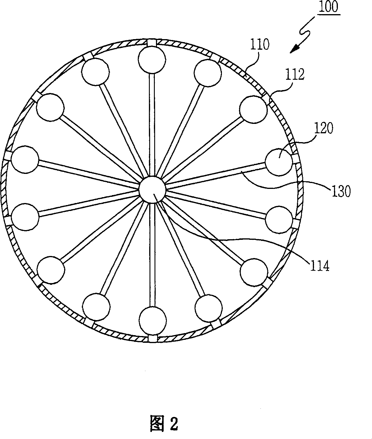
[0032] The features of the roller device according to the present embodiment include that the length of the region in which the vacuum suction force is applied can be varied according to the specifications of the film-like member to be attached. To this end, as shown in FIG. 2, the drum 100 according to the present embodiment includes: an adsorption drum 110; a vacuum pipe 120; a connecting member 130; a vacuum section regulator 140;

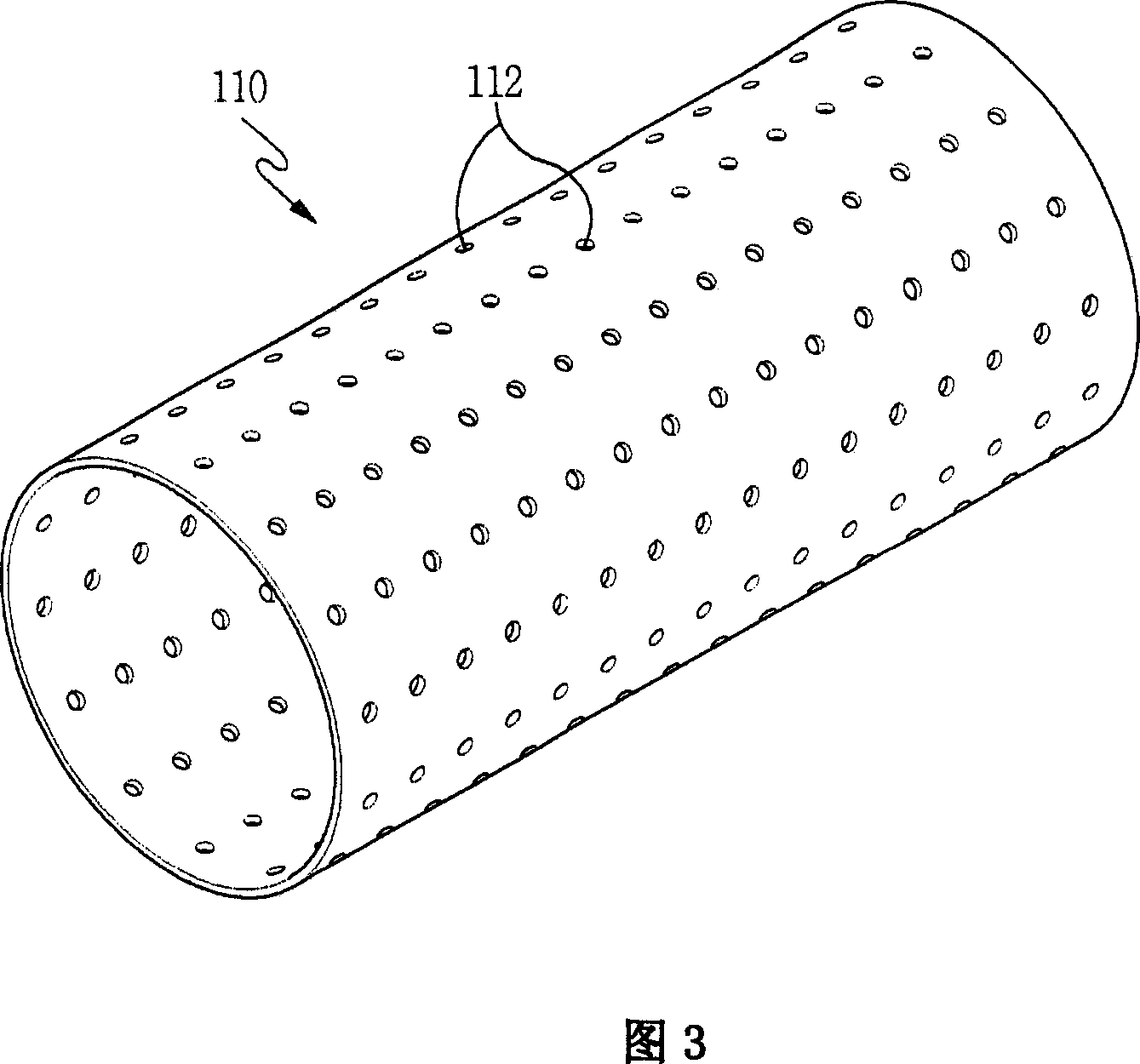
[0033] As shown in FIG. 3, the adsorption roller 110 has a large-diameter cylindrical structure whose circumference is larger than the long side of the conventional largest membrane member. The entire surface of the adsorption roller 110 is punched with a plurality of adsorption holes 112 . Specifically, a plurality of suction holes 112 are uniformly punched on the cylinder having a predetermined thickness to allow the membrane member to be attached to the outer peripheral surface of the cylinder by suction. In this case, it is preferable that ...

no. 2 example

[0047] The features of the roller device 200 according to the present embodiment include that a plurality of vacuum suction sections having different lengths from each other are defined on the outer peripheral surface of the device 200 to correspond to the specification of the membrane member to be attached. For this, as shown in FIG. 7 , the roller device 200 according to the present embodiment includes: a suction roller 210 ; a vacuum pad 220 ; a connection part 230 ; and a roller rotator (not shown).

[0048] Similar to the first embodiment, a plurality of vacuum suction holes 212 are formed on the entire surface of the adsorption roller 210 . The adsorption roller 210 is a constituent element that allows a film member to be attached to its outer peripheral surface.

[0049] A vacuum pad 220 is disposed inside the suction drum 210 to connect with the suction holes 212 . The vacuum pad 220 is a constituent element that applies vacuum suction force to the suction holes 212 ....


PUM

PropertyMeasurementUnit
Diameteraaaaaaaaaa

Abstract

The present invention discloses a roll device used for adhering a membrane part to any surface of a flat panel display equipment unit. The roll device is characterized in that, the length of an area to be applied a vacuum adsorptive power is capable of changing according to the specification of the membrane part to be adhered.

Description

technical field [0001] The present invention relates to a roller device for use in the operation of attaching a membrane member to any surface of a flat panel display device unit. Background technique [0002] Recently, as the modern society shifts toward informatization, the importance of information display devices has remarkably increased. Examples of information display devices mainly employed are liquid crystal displays (LCDs), plasma display panels (PDPs), organic light emitting devices (OLEDs), and the like. Among the above-mentioned information display devices, the importance of liquid crystal displays is gradually increasing nowadays. In particular, liquid crystal displays are attracting high attention as a substitute capable of overcoming problems with cathode ray tubes (CRTs), relying on various advantages such as small size, light weight, and low power consumption. Correspondingly, liquid crystal displays are gradually expanding in their fields of use. [0003...

Claims


Application Information

Patent Timeline
IPC IPC(8): G02F1/1335G02F1/1333
CPCB65B33/00G02B5/30G02F1/13H01L21/6838
Inventor 闵丙金
Owner ARCHER DANIELS MIDLAND CO
Why Eureka
Try Eureka