Stone material processing method and stone material saw
A stone cutting and stone processing technology, applied in stone processing tools, stone processing equipment, manufacturing tools, etc., can solve the problems that restrict the popularization and application of stone cutting saws, difficult manufacturing, low cutting efficiency, etc., and achieve improved cutting conditions, lubricated And the effect of good cooling conditions and high cutting pressure
- Summary
- Abstract
- Description
- Claims
- Application Information
AI Technical Summary
Problems solved by technology
Method used
Image
Examples
Embodiment 1
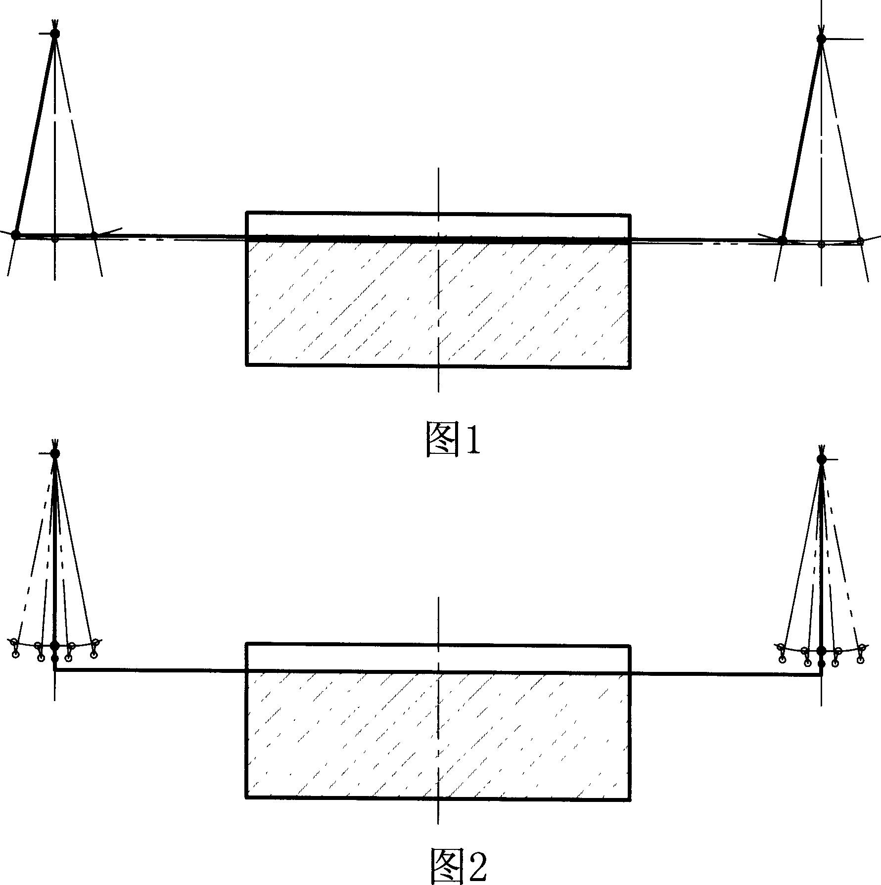
[0022] As shown in Figure 5, the body is composed of four uprights 1 and a lifting platform 3 matched with the upright column 1. Each upright has a lead screw, and the screw nut matched with it is fixedly connected to the lifting platform 3, and the upper end of the swing arm 4 is connected to the lifting platform 3. The upper part of the column 1 is hinged, and the work table 13 and the stone material are lifted and lowered by the lifting table 3 during use, so as to realize the feeding of the stone and the cutting of the stone. Two swing arms 4 of equal length. The lower end of the swing arm 4 is hinged to a saw frame 7. The saw frame 7 is connected to the connecting rod 8 in the crank connecting rod mechanism. The crank connecting rod mechanism is driven by the motor 9 and is arranged between the crank connecting rod mechanism and the motor. There are a flywheel 10 and a transmission belt 5, and the flywheel 10 and the motor 9 are connected by the transmission belt 5. In the cr...
Embodiment 2
[0024] As shown in Figure 5, only the diamond saw blade in Example 1 was replaced with a sand saw blade.
Embodiment 3
[0026] As shown in Figure 6, there are two swing arms 4 of equal length. The lower end of the swing arm 4 is hinged to a saw frame 7. The saw frame 7 is connected to the connecting rod 8 of the crank connecting rod mechanism. The crank connecting rod mechanism is driven by the motor 9 and the crank connecting rod mechanism. A flywheel 10 and a transmission belt 5 are arranged between the flywheel and the motor, and the flywheel 10 and the motor 9 are connected by the transmission belt 5. In the crank connecting rod mechanism, one end of the crank 11 is fixedly connected to the flywheel 10, and the other end is fixedly connected to the central axis of the flywheel 10. With this structure, the single-sided swing of the swing arm 4 can enable the saw blade 6 to continuously cut throughout the entire stroke. The axis distance between the two hinge shafts 2 at the upper end of the two swing arms 4 is smaller than the axis distance between the two hinge shafts 2 at the lower end of the ...
PUM
 Abstract
Description
Claims
Application Information
 - R&D
- Intellectual Property
- Life Sciences
- Materials
- Tech Scout
- Unparalleled Data Quality
- Higher Quality Content
- 60% Fewer Hallucinations
Browse by: Latest US Patents, China's latest patents, Technical Efficacy Thesaurus, Application Domain, Technology Topic, Popular Technical Reports.
© 2025 PatSnap. All rights reserved.Legal|Privacy policy|Modern Slavery Act Transparency Statement|Sitemap|About US| Contact US: help@patsnap.com


