

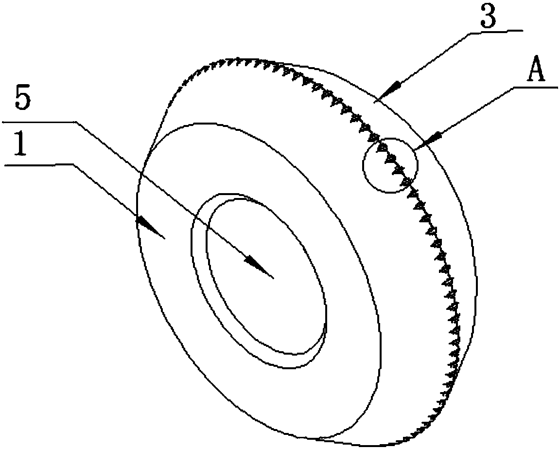
Knife wheel with platforms
A platform and cutter wheel technology, applied in the field of cutter wheels with a platform, can solve problems such as wear, small contact area, and high cutting pressure, and achieve the effects of uniform crack depth, enlarged cutting range, and small tangent damage
- Summary
- Abstract
- Description
- Claims
- Application Information
AI Technical Summary
Problems solved by technology
Method used
Image

Examples
Embodiment 1
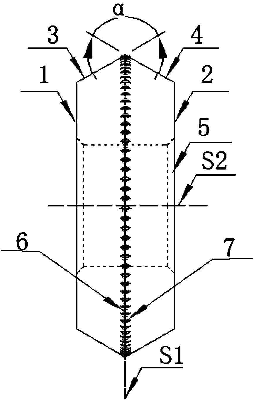
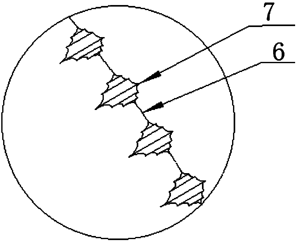
[0040] In this embodiment, the side view structure of the groove 7 is as Figure 4 Shown. The first groove wall 71 and the second groove wall 72 are symmetrical about the transverse central section S2 of the cutter wheel, and the platforms 73 are both convex arc-shaped platforms, extending from the circumferential edge 6 to the bottom of the groove 7 In terms of the above, the height h between adjacent platforms gradually increases, and the angle θ between adjacent platforms gradually increases. As the distance between the two cones gradually increases, the surface area of the platform gradually increases.
[0041] In this embodiment, while the angle θ gradually increases every 10°, the height h of the platform gradually increases every 0.5um, so as to ensure that each platform participates in cutting.
[0042] It should be noted that the arc-shaped platform in this example can only be convex but not concave, otherwise it will not play the role of secondary cutting. The cutting ...
Embodiment 2
[0044] In this embodiment, the side view structure of the groove 7 is as Figure 5 Shown. The first groove wall 71 and the second groove wall 72 are symmetrical with respect to the transverse central section S2 of the cutter wheel, and the platforms 73 are both convex trapezoidal platforms, in the extending direction from the circumferential edge 6 to the bottom of the groove 7 , The height h of adjacent platforms gradually increases, and the angle θ between adjacent platforms gradually increases. As the distance between the two cones gradually increases, the surface area of the platform gradually increases. As a linear platform, the convex trapezoidal platform can make the cutter wheel have the advantages of small tangent line damage, smooth cutting line, flat cutting section, and uniform crack depth. In this embodiment, while the included angle θ gradually increases every 5°-10°, the height h of the platform gradually increases every 0.2-0.5um to ensure that each platform p...
PUM
| Property | Measurement | Unit |
|---|---|---|
| Diameter | aaaaa | aaaaa |
| Thickness | aaaaa | aaaaa |
Abstract
Description
Claims
Application Information