
Stone material processing method and stone material saw

A stone cutting and frame sawing technology, applied in stone processing tools, stone processing equipment, manufacturing tools, etc., can solve the problems of restricting the popularization and application of stone cutting saws, high manufacturing difficulty, low cutting efficiency, etc., and achieves improved cutting conditions and lubrication. And the effect of good cooling conditions and high cutting pressure

Inactive Publication Date: 2010-08-18
山东华兴机械股份有限公司
View PDF0 Cites 0 Cited by
  • Summary
  • Abstract
  • Description
  • Claims
  • Application Information

AI Technical Summary

Problems solved by technology

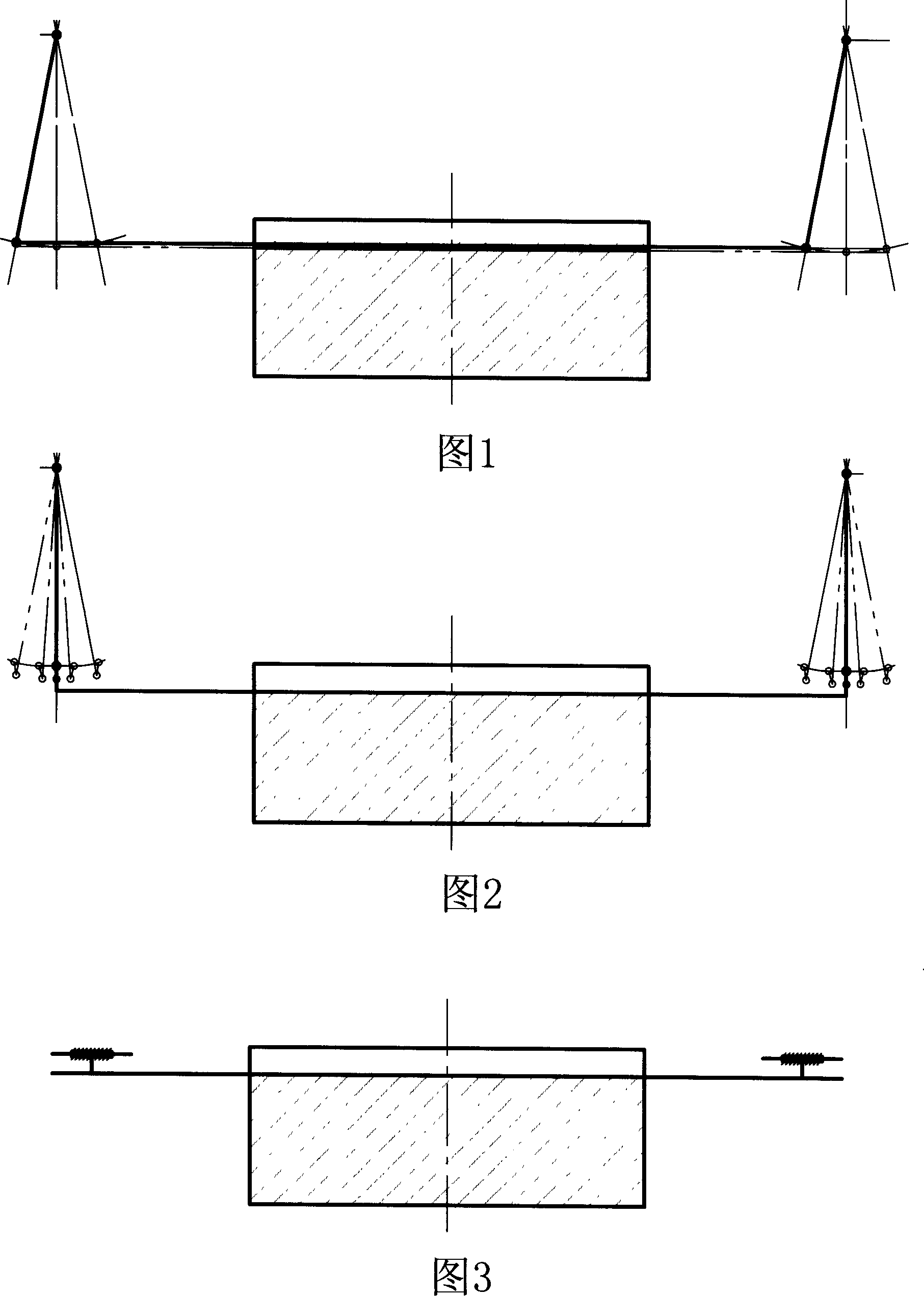
[0002] At present, the oscillating stone cutting saw has a saw frame with many saw blades installed. The saw frame is connected to the swing arm. The drive device makes the saw frame reciprocate along the movement track of the swing arm to complete the cutting of the stone. The saw frame reciprocates. There are single pendulum type as shown in Figure 1, translational type as shown in Figure 2, and three modes of straight-to-curve as shown in Figure 3. During the cutting process of the three modes, the saw frame is always kept parallel to the cutting surface of the stone, and the cutting surface of the saw blade is completely in line with the stone. Contact, the cutting pressure of the saw blade on the stone is small, so the cutting efficiency of the traditional stone cutting saw is low, and the production efficiency can only be improved by increasing the weight of the equipment, resulting in high cost and difficult manufacturing, which seriously restricts the popularization and application of stone cutting saws

Method used


Image

  • Stone material processing method and stone material saw
  • Stone material processing method and stone material saw
  • Stone material processing method and stone material saw

Examples


Embodiment 1

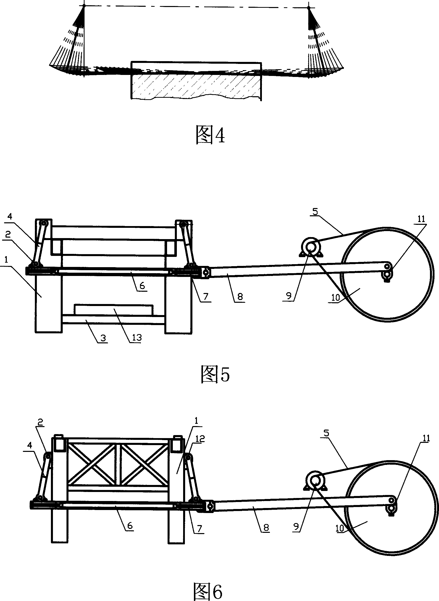
[0022] As shown in Figure 5, the body is made up of four uprights 1 and an elevating platform 3 that cooperates with the uprights 1. A lead screw is arranged on each upright, and the screw nut that cooperates with it is fixedly connected with the elevating platform 3, and the upper end of the swing arm 4 is connected with the elevating platform 3. The upper part of the column 1 is hinged. During use, the lift table 3 lifts the workbench 13 and the stone to lift, so as to realize the feeding of the stone and cut the stone. Two swing arms 4 with equal length, the lower ends of the swing arms 4 are hinged to the saw frame 7, the saw frame 7 is connected to the connecting rod 8 in the crank linkage mechanism, the crank linkage mechanism is driven by the motor 9, and the crank linkage mechanism and the motor are arranged There are flywheel 10 and transmission belt 5, and flywheel 10 is connected with motor 9 by transmission belt 5. The crank 11 in the crank-link mechanism has one e...

Embodiment 2

[0024] As shown in Figure 5, only the diamond saw blade in Embodiment 1 is replaced with a sand saw blade.

Embodiment 3

[0026] As shown in Figure 6, two swing arms 4 with equal lengths, the lower ends of the swing arms 4 are hinged to the saw frame 7, the saw frame 7 is connected to the connecting rod 8 in the crank linkage mechanism, the crank linkage mechanism driven by the motor 9, and the crank linkage mechanism A flywheel 10 and a transmission belt 5 are arranged between the motor and the motor, and the flywheel 10 is connected with the motor 9 through the transmission belt 5 . In the crank-link mechanism, the crank 11 has one end fixedly connected to the flywheel 10, and the other end fixedly connected to the central axis of the flywheel 10. The unilateral swing of the swing arm 4 of this structure can make the saw blade 6 cut continuously in the whole stroke. The axial distance between the two hinge shafts 2 at the upper ends of the two swing arms 4 is smaller than the axial distance between the two hinge shafts 2 at the lower ends of the two swing arms 4, so that the cutting trajectory o...


PUM


Abstract

The present invention is stone material processing method and stone material cutting saw. The stone material processing method features that the saw blade is made to swing along one arc track so as to form point contact with stone material during cutting. The corresponding stone material cutting saw features that the interval between two upper hinge axes of the swinging arm is not equal to that between two lower hinge axes. Compared with traditional stone material cutting technology, the present invention has the advantages of raised production efficiency, and lowered apparatus maintenance cost.

Description

technical field [0001] The invention relates to a stone processing machine, in particular to a stone processing method and a stone cutting saw for realizing the method. Background technique [0002] At present, the oscillating stone cutting saw has a saw frame with many saw blades installed. The saw frame is connected to the swing arm. The drive device makes the saw frame reciprocate along the movement track of the swing arm to complete the cutting of the stone. The saw frame reciprocates. There are single pendulum type as shown in Figure 1, translational type as shown in Figure 2, and three modes of straight-to-curve as shown in Figure 3. During the cutting process of the three modes, the saw frame is always kept parallel to the cutting surface of the stone, and the cutting surface of the saw blade is completely in line with the stone. Contact, the cutting pressure of the saw blade on the stone is small, so the cutting efficiency of the traditional stone cutting saw is low,...

Claims


Application Information

Patent Timeline
Patent Type & Authority Patents(China)
IPC IPC(8): B28D1/06
Inventor 李永王兆生张本利杨庆华王艳芳
Owner 山东华兴机械股份有限公司
Learn More