
Flow-throttling hole hydraulic buffer

A technology of hydraulic buffers and orifices, applied in the field of hydraulic buffers, can solve the problems of small operating temperature range, impact on buffering performance, and inability to fully exert the buffering effect, and achieve the effect of wide operating temperature range and stable buffering performance

Inactive Publication Date: 2007-06-13
710TH RES INST OF CHINA SHIPBUILDING IND CORP
View PDF0 Cites 11 Cited by
  • Summary
  • Abstract
  • Description
  • Claims
  • Application Information

AI Technical Summary

Problems solved by technology

However, the current hydraulic buffer has two major defects: one is poor adaptability to impact speed
When the equipment fails, the speed at which it hits the buffer is not the same each time. When designed according to high speed, the buffering effect cannot be fully exerted at low speed; when designed according to low speed, the equipment cannot be well protected during high-speed failure; the second is the operating temperature range Small
The ship has a wide range of activities, the ambient temperature often changes, and the viscosity of the hydraulic oil also changes accordingly, resulting in a change in the cushioning stiffness and greatly affecting the cushioning performance

Method used


Image

  • Flow-throttling hole hydraulic buffer

Examples


Embodiment Construction

[0012] Below in conjunction with accompanying drawing and embodiment the present invention is described in further detail:

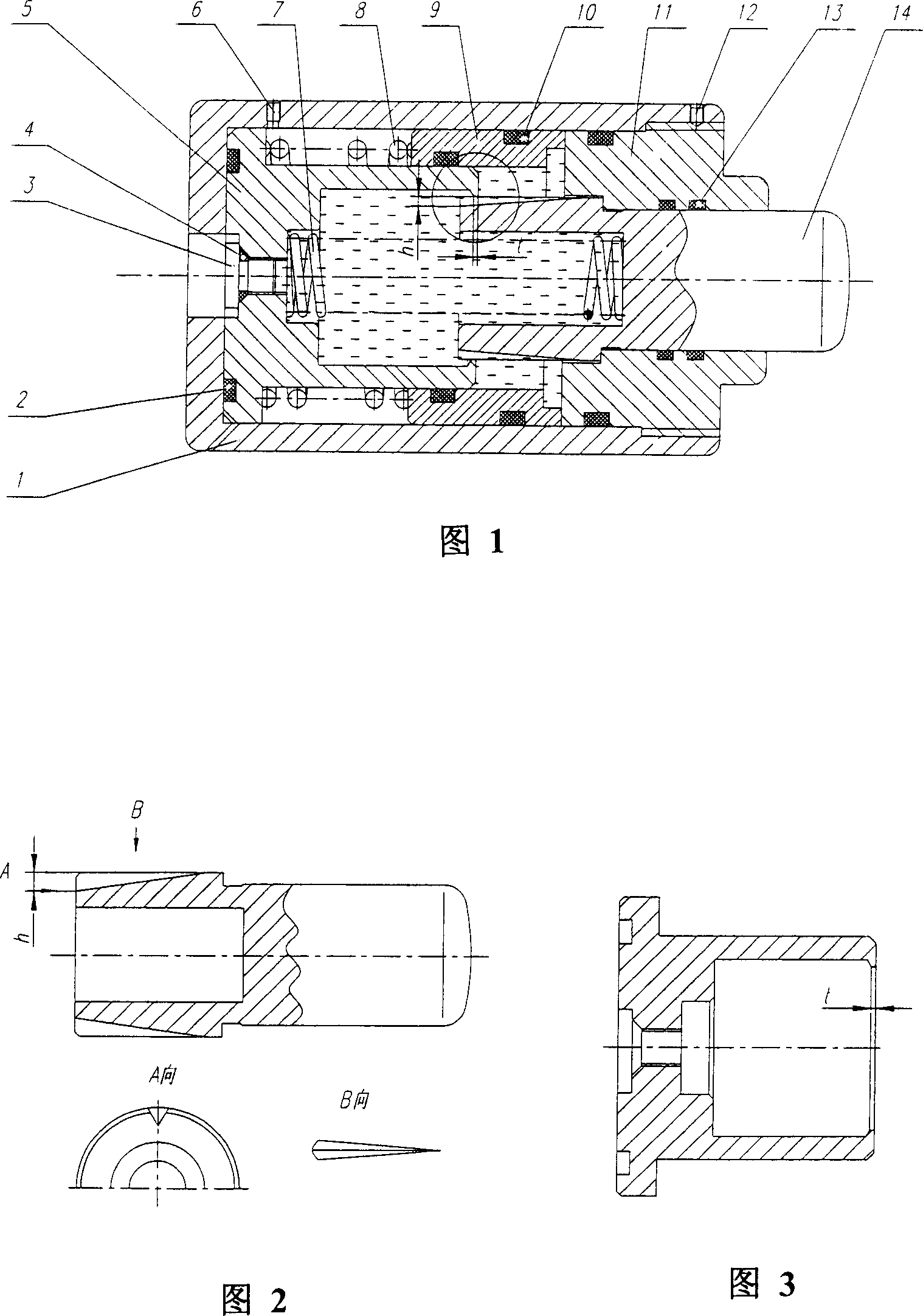
[0013] As shown in Figure 1, serial number 1 is a cylindrical shell, which is equipped with buffer parts, hydraulic oil and seals inside, and equipped with equipment installation interfaces on the outside. Serial numbers 2, 4, 10, and 13 are O-rings to prevent hydraulic oil from leaking. No. 3 is the filling screw plug, which can add or discharge hydraulic oil from the screw hole after unscrewing it. The throttling wall 5 has a cylindrical shape and an inner cavity, the left end of which matches the inner circle of the housing 1, and the outer circle of the right end matches the inner circle of the pressurized sliding sleeve 9, and the thickness of the right end of the inner circle is t (see Figure 3). The throttling wall is thick, and the inner circle of the right end of the throttling wall 5 cooperates with the outer circle of the left end of the buff...


PUM


Abstract

The invention discloses a throttling orifice hydraulic buffer. It includes buffer body, inner and outer back springs, throttling wall, supercharge sliding sleeve, buffering contact. The cylindrical surface of the buffering contact and the throttling wall is set two grooves set throttling orifice to block oil moving. The invention has impact velocity automatic adaptability, can keep shock absorbing capacity stable by adapting the variety of the hydraulic oil viscosity under major temperature variety.

Description

technical field [0001] The invention relates to a hydraulic buffer technology, in particular to an orifice hydraulic buffer. Background technique [0002] The buffer is also called the limit protector, which is an important part of many equipment to protect itself. When absorbing the same energy, the volume of the mechanical buffer is much larger than that of the hydraulic buffer, and there is rebound after buffering; the hydraulic buffer is small in size and heavy in weight. It is light, can increase the use space of the equipment, has no rebound when buffering, the equipment bears small impact force, small vibration, and small deceleration, thus prolonging the life of the equipment. Marine equipment is required to be small in size and light in weight, so hydraulic buffers are getting more and more attention in the development of marine equipment. However, the current hydraulic buffer has two major defects: one is poor adaptability to impact speed. When the equipment fail...

Claims


Application Information

Patent Timeline
Patent Type & Authority Applications(China)
IPC IPC(8): F16F9/34
Inventor 黄朝学田启华张毅敏蔡蒨肖本德孟遂民
Owner 710TH RES INST OF CHINA SHIPBUILDING IND CORP
Learn More