Supercharge Your Innovation With Domain-Expert AI Agents!

Combination spout stop/bottom bushing.

A nozzle and bushing technology, which is applied in the field of faucets, can solve the problems of entanglement of the nozzle pulling out the hose, water spraying, etc.

Inactive Publication Date: 2007-06-13
NEWFREY
View PDF0 Cites 3 Cited by
  • Summary
  • Abstract
  • Description
  • Claims
  • Application Information

AI Technical Summary

Problems solved by technology

However, one problem with this design is that the nozzle may be rotated so much that water sprays onto the countertop behind the sink
Additionally, the nozzle may be rotated a full 360 degrees and beyond in some configurations, which can cause tangling of the pull-out hose located within the nozzle

Method used


Image

  • Combination spout stop/bottom bushing.
  • Combination spout stop/bottom bushing.
  • Combination spout stop/bottom bushing.

Examples


Embodiment Construction

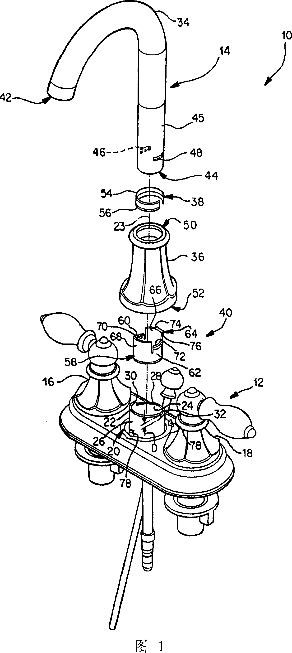
[0015] Referring now to the drawings and in particular to FIG. 1, there is shown a faucet assembly 10 embodying the invention.

[0016] The faucet part 10 includes a faucet housing 12 and a spout part 14 .

[0017] The faucet housing 12 has installed therein a hot water valve part 16 and a cold water valve part 18 . The faucet housing 12 includes a body 20 for rotatably mounting the spout member 14 . The body 20 comprises a cylindrical element 22 with a shaft 23 .

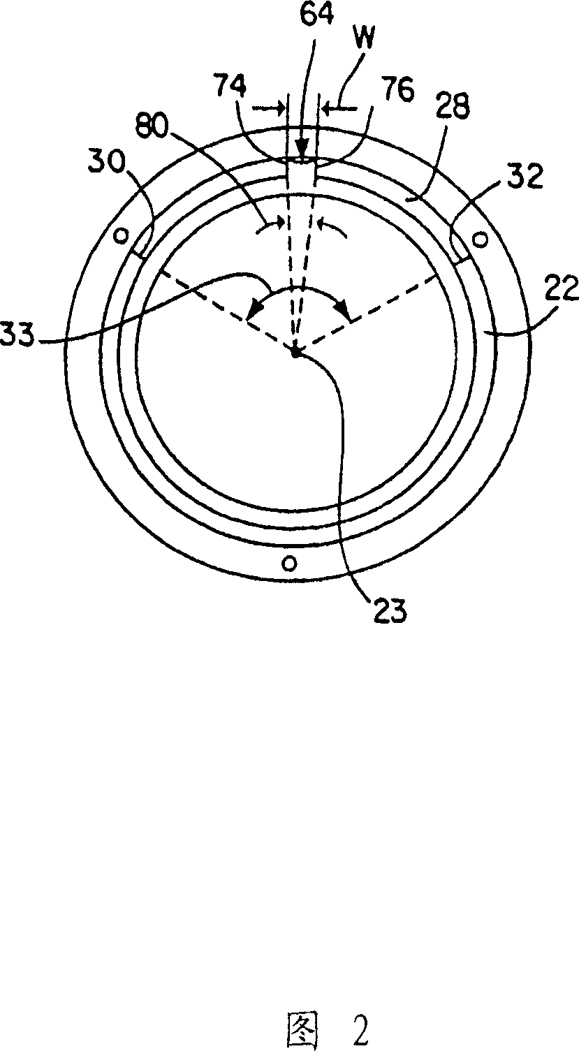
[0018] Referring also to FIG. 2 , cylindrical member 22 includes an inner surface 24 , an outer surface 26 , and an annular passage 28 defining a pair of rotation limiting members 30 , 32 . The annular passage 28 and the rotation limiting parts 30, 32 may be formed in the cylindrical member 22, for example, by removing an annular portion of the cylindrical member 22, thereby forming an incision having a predetermined depth D and providing the rotation limiting parts 30, 32 A predetermined angular distance at an ...


PUM


Abstract

A faucet assembly includes a faucet housing including at least one rotational limit feature positioned with respect to an axis. A spout assembly includes a spout, the spout having attached thereto a stop member positioned to engage the rotational limit feature when the spout is rotated about the axis.

Description

technical field [0001] This invention relates to a faucet and, more particularly, to a combination spout stop and bottom bushing for use on a faucet. Background technique [0002] A typical faucet, such as a kitchen faucet, has a movable spout that can be rotated to supply water to a predetermined location, for example, to either of two sinks. However, one problem associated with this design is that the nozzle may be rotated so much that water sprays onto the countertop behind the sink. Additionally, the nozzle may be rotated a full 360 degrees and beyond in some constructions, which may cause tangling of the pull-out hose located within the nozzle. Contents of the invention [0003] The present invention provides a limiting stop device for a nozzle so that the nozzle can only be rotated by a fixed angle, for example about 150 degrees instead of 360 degrees. [0004] One form of the invention proposes a faucet component. The faucet component includes a faucet housing in...

Claims


Application Information

Patent Timeline
Patent Type & Authority Applications(China)
IPC IPC(8): E03C1/04B67D9/02
CPCE03C1/04
Inventor 埃文·A·本斯特德
Owner NEWFREY
Features
  • R&D
  • Intellectual Property
  • Life Sciences
  • Materials
  • Tech Scout
  • Unparalleled Data Quality
  • Higher Quality Content
  • 60% Fewer Hallucinations
Learn More