Follow-up detector for two dimension moving point steel cable tension and displacement

A detection device, wire rope technology, applied in the direction of tension measurement, the use of optical devices to transmit sensing components, etc.

Inactive Publication Date: 2007-06-27
CHINA UNIV OF GEOSCIENCES (WUHAN)
View PDF0 Cites 34 Cited by
  • Summary
  • Abstract
  • Description
  • Claims
  • Application Information

AI Technical Summary

Problems solved by technology

When this process is in the middle and deep holes (wells), the technicians command the operation base

Method used


Image

  • Follow-up detector for two dimension moving point steel cable tension and displacement
  • Follow-up detector for two dimension moving point steel cable tension and displacement
  • Follow-up detector for two dimension moving point steel cable tension and displacement

Examples


Embodiment Construction

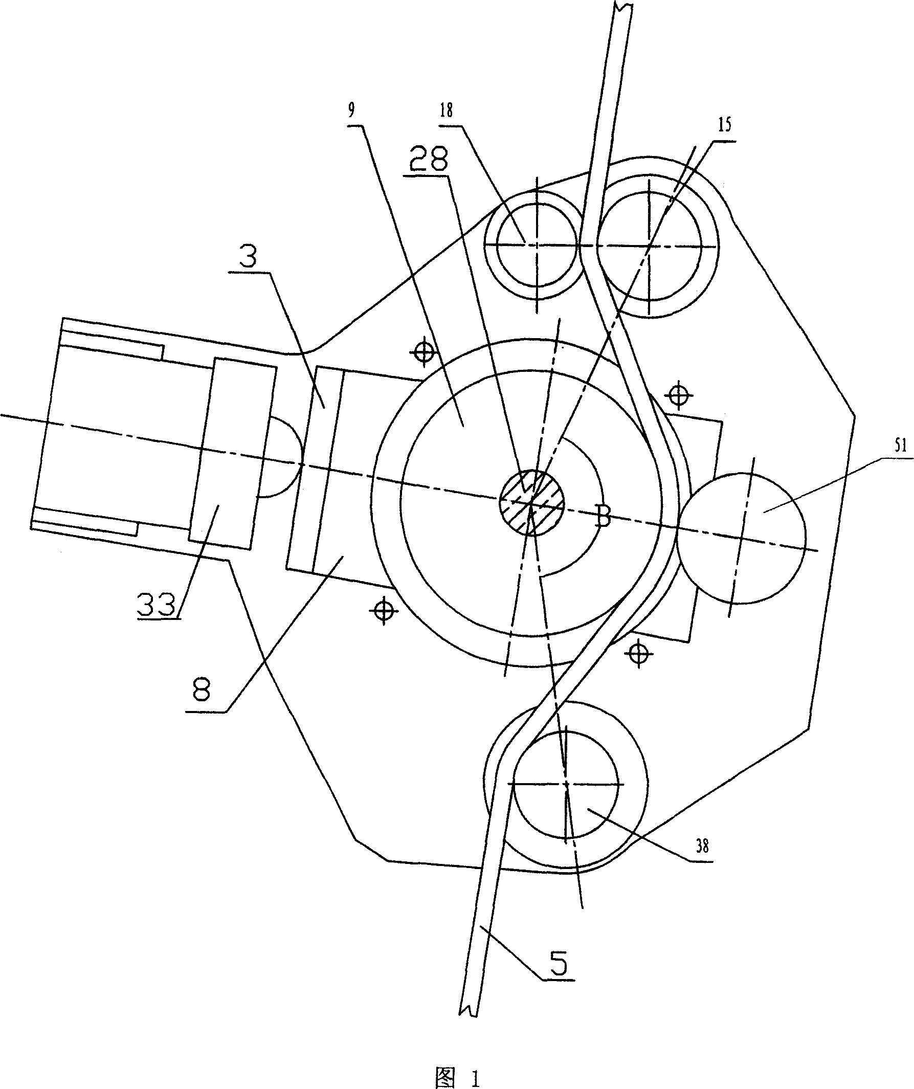
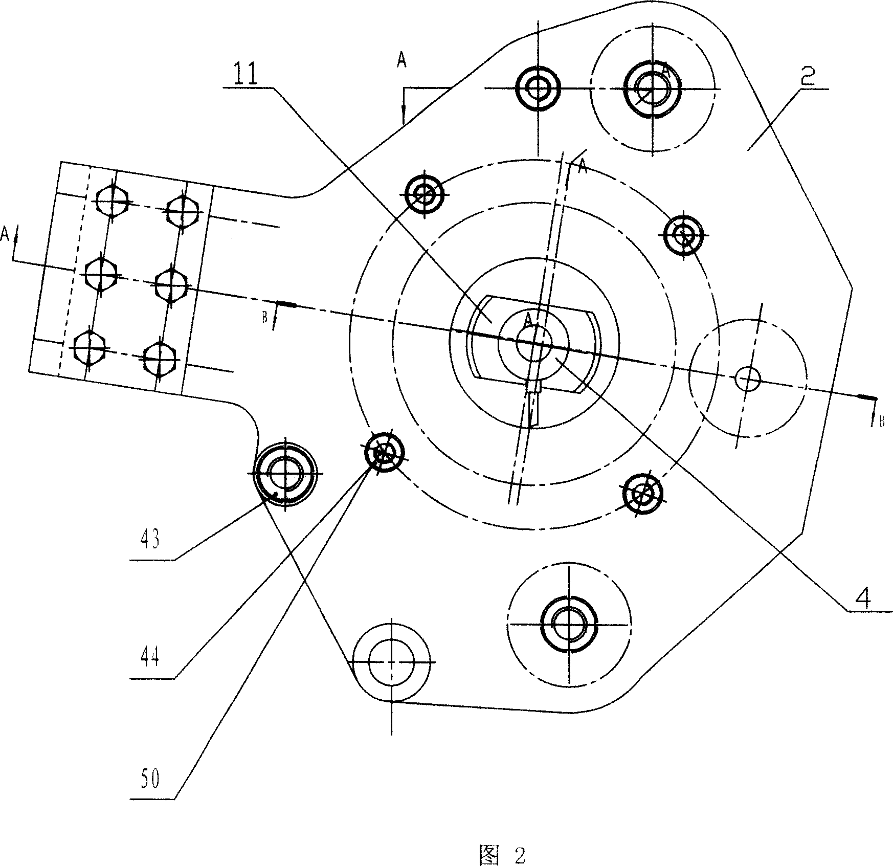
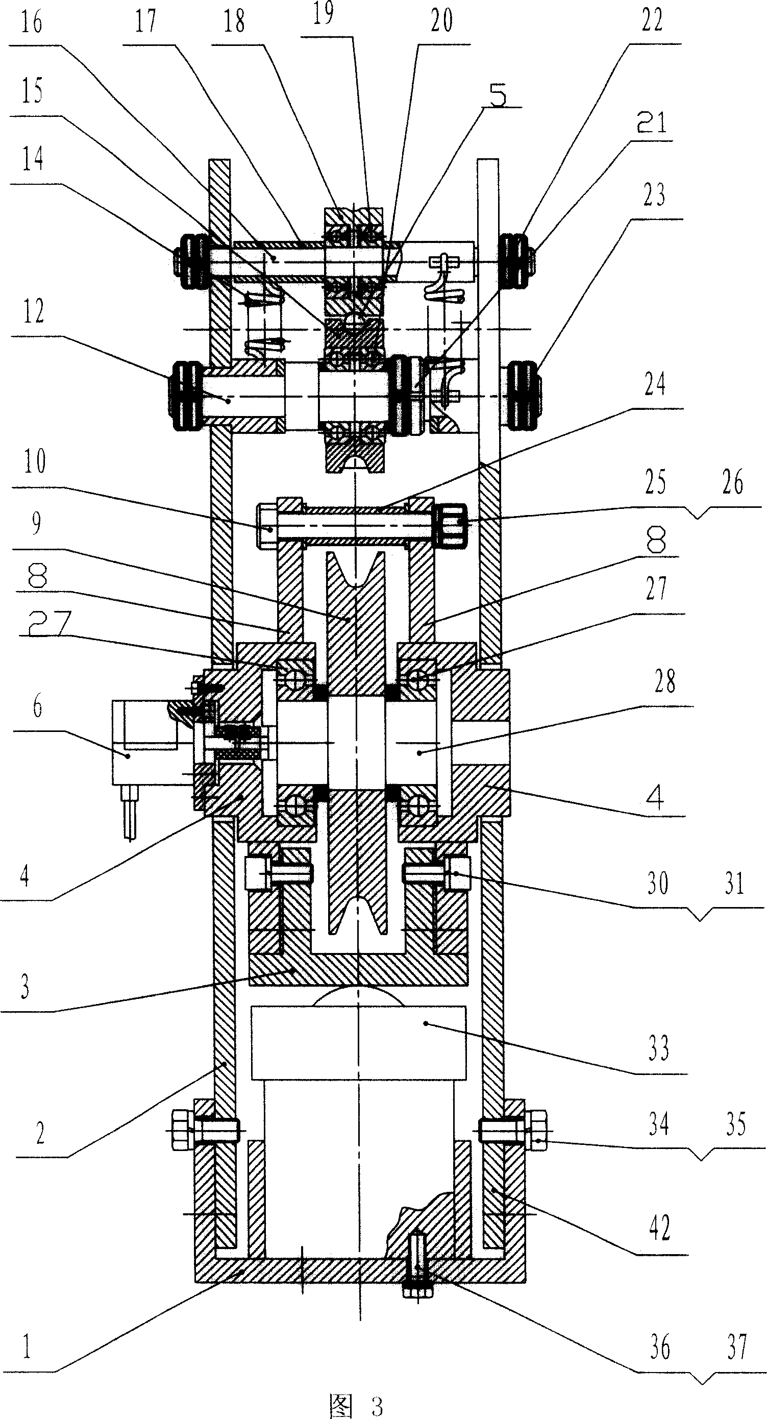
[0016] Further illustrate the embodiment of the present invention below in conjunction with accompanying drawing, as Fig. 1, the technical scheme that the present invention solves the problems of the technologies described above is: steel wire rope 5 penetrates from lower pulley 38, reaches upper pulley 15 through large pulley 9 and passes through, and large pulley 9 is fixed on the big wheel shaft 28, and the rotary encoder 6 is fixed on one end of the big wheel shaft 28. When the steel wire rope 5 moves up and down, it drives the big pulley 9 and the moving disk of the rotary encoder 6 to rotate. In theory, every time the big pulley 9 rotates , the wire rope 5 will move the large pulley 9 for a distance of circumference s, and the rotary encoder 6 will send n pulses, so the length L=k that the steel rope moves can be measured according to the number m of pulses sent by the rotary encoder 6 · m (the coefficient k=s / n in the formula). Of course, due to slipping between the wir...


PUM


Abstract

The measuring device includes a pressure sensor, and a rotary encoder. Characters are that the rotary encoder is fixed on one end of bull wheel spindle; being fixed on inner side plate, the slide and the top plate are connected to form a float measurement rack; the pressure sensor is installed on side of the top plate; slide holes on left side plate and right side plate are present in rectangle on central axis of the pressure sensor. Being installed at place near to exit of rope from the hoist drum, the measuring device carries out 2D follow-up measuring for tensile force and displacement when steel wire rope moves along axis and radial direction of the hoist drum. The invention provides operable technical support for automatic detection and automation control. The invention is widely applicable to harbors, engineering hoisting, and resource exploration development industries for ex. mine, geology, and ocean etc.

Description

technical field [0001] The invention relates to a force and displacement measuring device, in particular to a two-dimensional moving point steel wire rope, a steel cable tension and displacement follow-up detection device. Background technique [0002] Usually the tension of the wire rope is measured at the end of the wire rope, or the wire rope passes through the fixed pulley, and a load cell is installed in the center of the support seat of the fixed pulley for measurement; the measurement of the moving distance of the wire rope is at the end of the wire rope, or the wire rope passes through a fixed pulley. The pulley block drives the rotary encoder on the wheel shaft for measurement. However, this method of fixed-point force measurement and rope movement is not practical under the specific working conditions of some winches. For example, the rope coring process in geological exploration is a process in which the overshot suspended at the moving rope end of the coring win...

Claims


Application Information

Patent Timeline
IPC IPC(8): G01L5/10G01D5/36
Inventor 江进国吴来杰吴晓光文国军饶建华李波杨杰
Owner CHINA UNIV OF GEOSCIENCES (WUHAN)
Why Eureka
Try Eureka