
Image forming apparatus and conveyance device

A conveying device and image technology, which are applied in the direction of electric recording process applying charge pattern, equipment for electric recording process applying charge pattern, electric recording technique, etc., can solve the problem that paper skew correction cannot be performed well, and driving timing changes. and offset issues

Inactive Publication Date: 2007-06-27
FUJIFILM BUSINESS INNOVATION CORP
View PDF0 Cites 9 Cited by
  • Summary
  • Abstract
  • Description
  • Claims
  • Application Information

AI Technical Summary

Problems solved by technology

In this case, variations and deviations occur in the driving timing of the second transport roller, and skew correction of the paper cannot be performed well

Method used


Image

  • Image forming apparatus and conveyance device
  • Image forming apparatus and conveyance device
  • Image forming apparatus and conveyance device

Examples


Embodiment Construction

[0030] Exemplary embodiments of the present invention will be described in detail below with reference to the accompanying drawings.

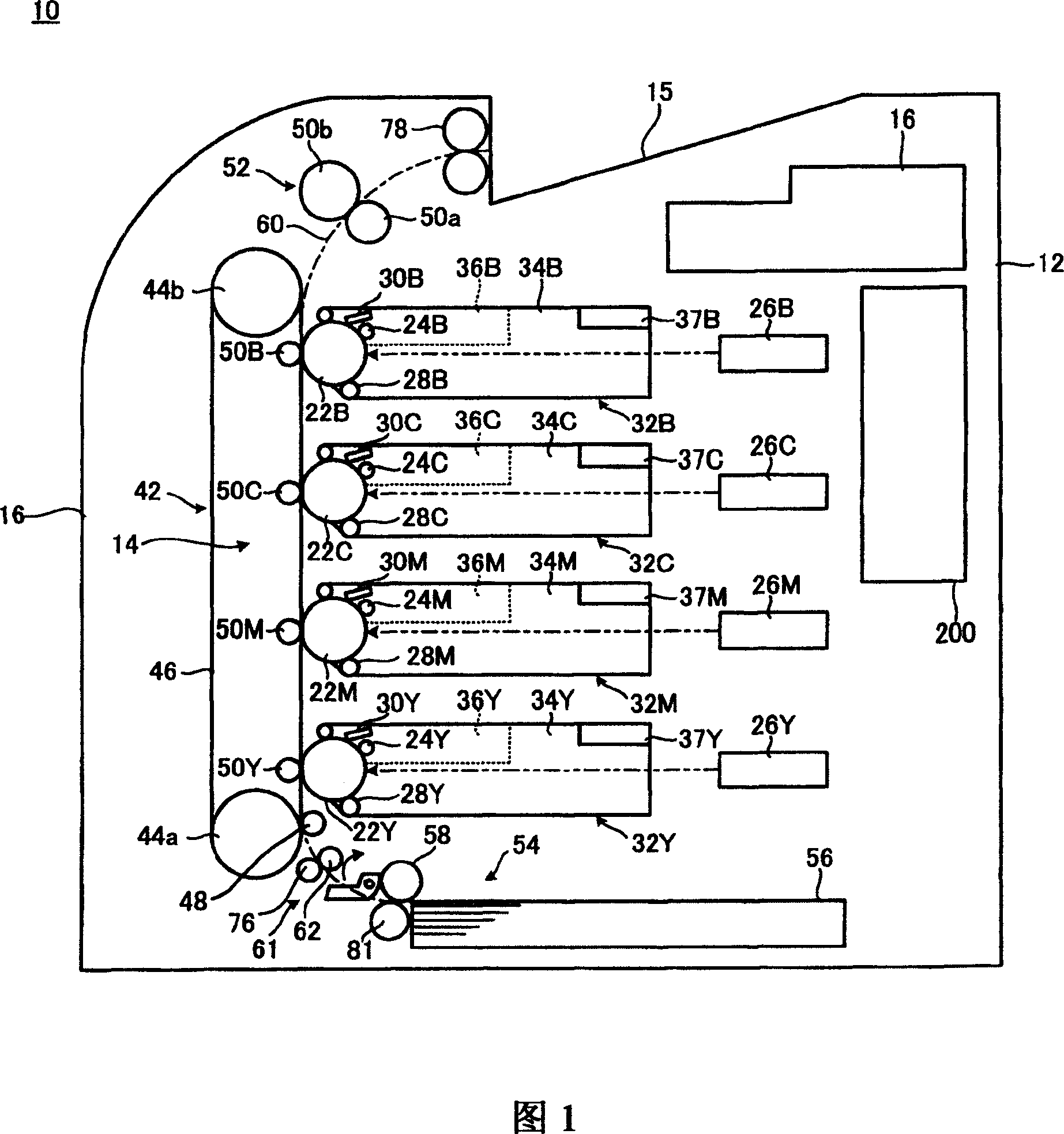
[0031] FIG. 1 shows an image forming apparatus 10 according to an exemplary embodiment of the present invention. The image forming apparatus 10 has an image forming apparatus main body 12 . The image forming apparatus main body 12 includes an image forming section 14 ; a paper feeder 54 that conveys paper to the image forming section 14 ; a power supply unit 16 ; and a controller 200 serving as control means. In addition, paper is discharged to a paper discharge portion 15 provided at an upper portion of the image forming apparatus main body 12 after image formation.

[0032]The image forming section 14 is an electrophotographic unit that forms a color image. The image forming section 14 has drum-shaped photoreceptors 22Y, 22M, 22C, and 22B as image holders that hold images of developing materials; 22M, 22C, and 22B uniformly charged chargin...


PUM


Abstract

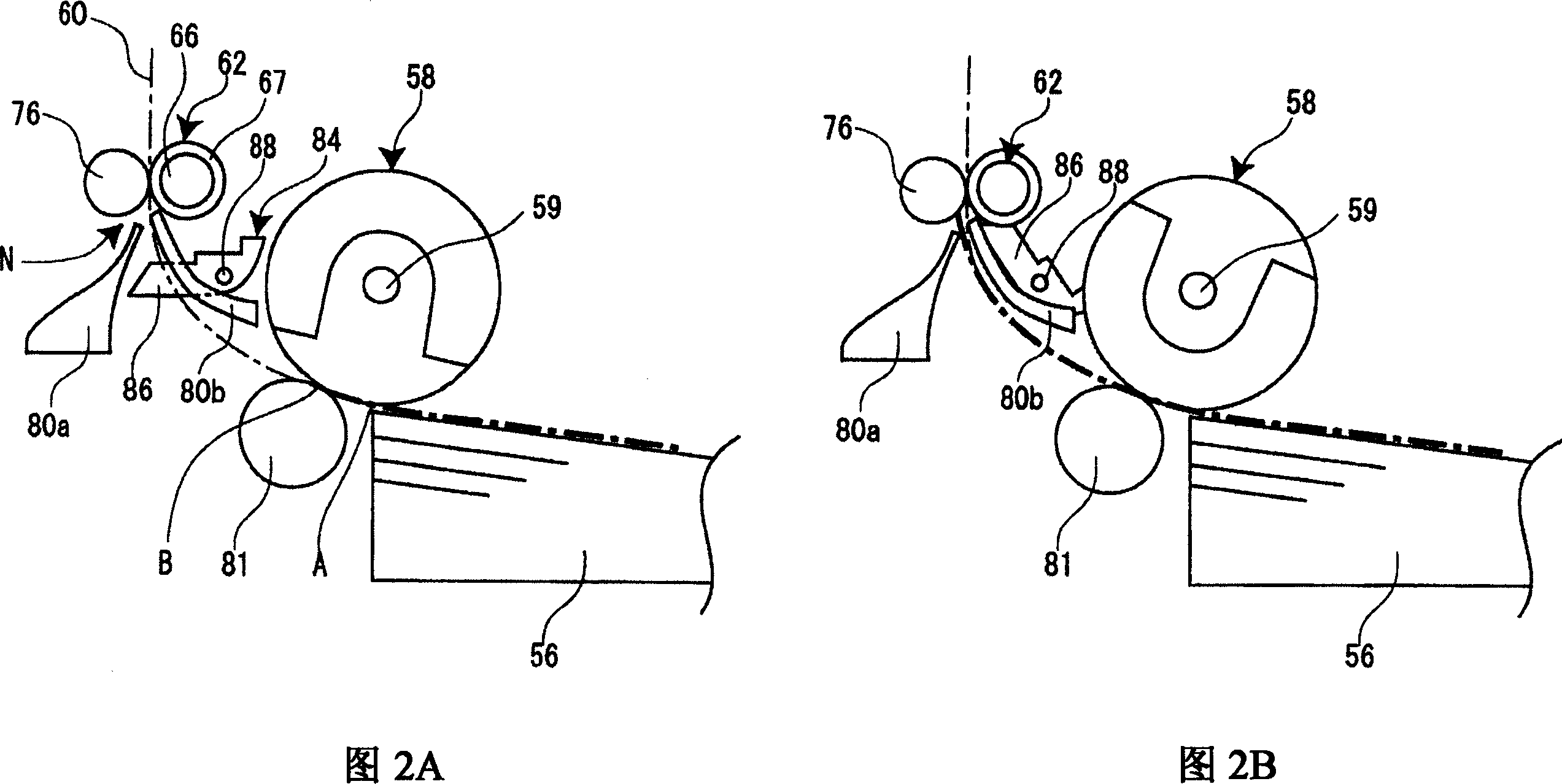
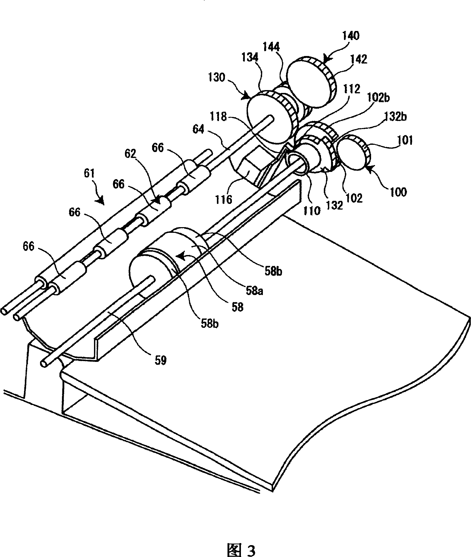
An image forming apparatus includes: an image forming part; a first conveyance roller that conveys a recording medium to the image forming part; a forward / reverse-rotatable second conveyance roller, located between the first conveyance roller and the image forming part in a conveyance direction of the recording medium; a contact member, in contact with the second conveyance roller, that forms a nip between the second conveyance roller and the contact member; a first conveyance roller driver that rotate-drives the first conveyance roller in the same direction as the conveyance direction of the recording medium; and a drive transmission mechanism that performs drive transmission from the first conveyance roller driver to the second conveyance roller so as to start rotation of the second conveyance roller in a reverse direction of the conveyance direction of the recording medium before a lead edge of the recording medium arrives at the nip.

Description

technical field [0001] The present invention relates to an image forming apparatus such as a copying machine, a facsimile machine, a printer, and the like and a conveying apparatus used in the image forming apparatus. Background technique [0002] In this type of image forming apparatus, there are equipped with a first conveying roller that conveys a recording medium such as paper to the image forming section; and a contact member, which is in contact with the second conveying roller to form a nip, and it is known to temporarily stop the leading edge of the recording medium at the nip during conveying so as to correct the skew of the recording medium. In addition, Japanese Published Unexamined Patent Application No. 2003-63698 discloses a technique of starting to rotate the second conveying roller toward the direction opposite to the conveying direction of the recording medium or conveyed matter, and stopping the second conveying roller. Reverse rotation of the rollers. ...

Claims


Application Information

Patent Timeline
Patent Type & Authority Applications(China)
IPC IPC(8): G03G15/00
CPCG03G2215/00405G03G15/6564G03G15/1665G03G15/6558G03G15/6567G03G15/00
Inventor 吉田和彦
Owner FUJIFILM BUSINESS INNOVATION CORP
Learn More