Body warp, warp letting off device of towel rapier loom

A technology of rapier looms and wool warp yarns, applied in looms, velvet looms, textiles, etc., to achieve the effects of improving cloth surface quality and loom efficiency, reducing resistance, and improving the rate of first-class products off the machine

Inactive Publication Date: 2007-07-11
邹荣金
View PDF0 Cites 5 Cited by
  • Summary
  • Abstract
  • Description
  • Claims
  • Application Information

AI Technical Summary

Problems solved by technology

[0004] The object of the present invention is to provide a bottom warp and wool warp let-off device of a terry rapier loom, which can effectively solve the above-mentioned deficiencies in the existing terry rapier looms

Method used


Image

  • Body warp, warp letting off device of towel rapier loom

Examples


specific Embodiment approach

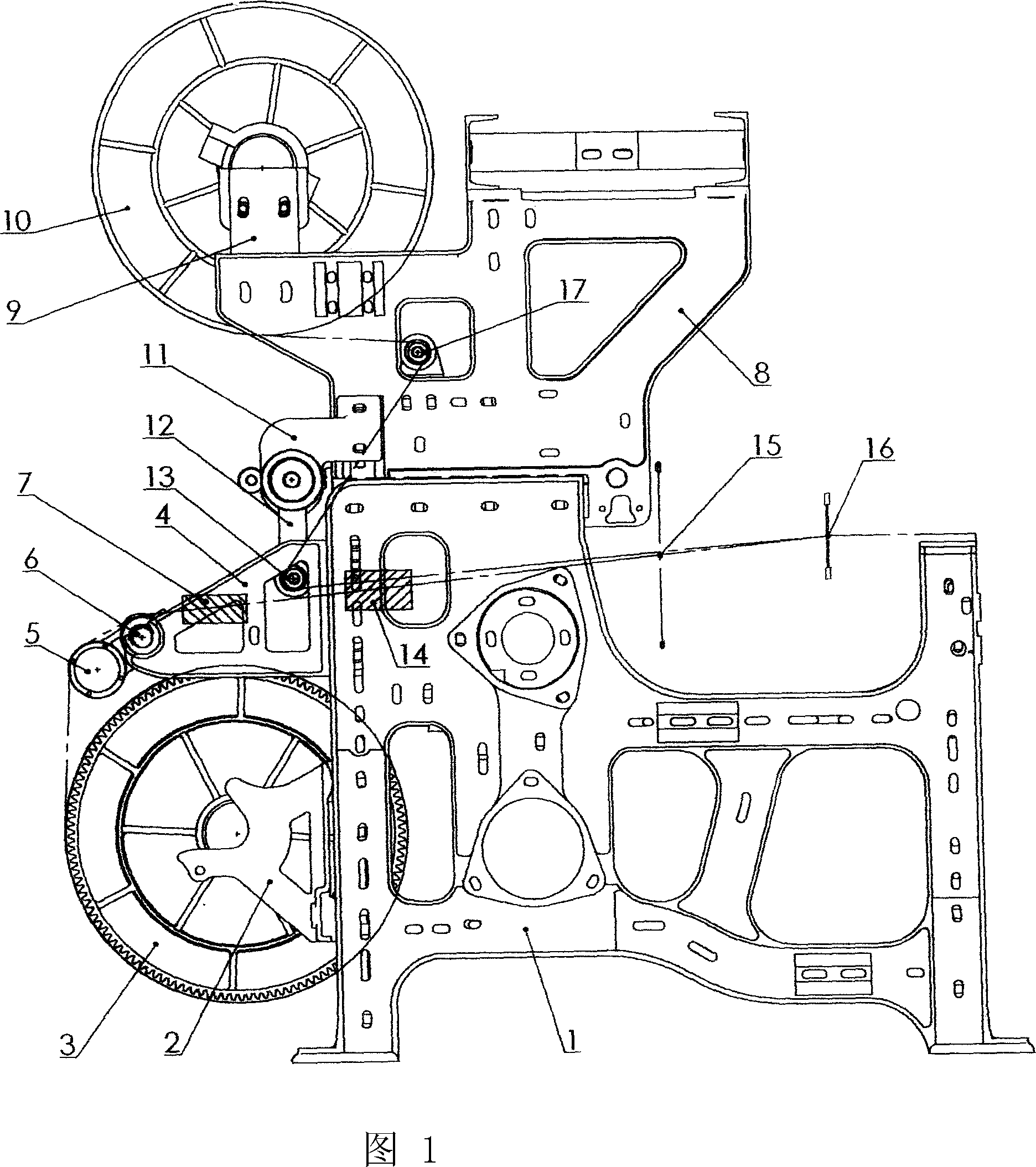
[0018] The warp breakage self-stop protection mechanism of the towel rapier loom includes a large wallboard 1, a bottom warp shaft support 2, a bottom warp shaft 3, a back beam support 4, a bottom warp tension roller 5, and a rear bar 6 , small wallboard 8, heightening wool warp beam support 9, wool warp beam 10, swing arm support 11, swing arm 12, wool warp yarn tension roller 13, heddle eye 15, weaving mouth 16, wool warp beam 10 passes through to increase Wool warp beam supporting foot 9 is fixed on the small wallboard 8, is provided with woolen warp thread guide roller 17 between woolen warp beam 10 and woolen warp yarn tension roller 13, is provided with between rear bar 6 and woolen warp yarn tension roller 13 Bottom warp yarn electronic warp stop device 7; wool warp yarn electronic warp stop device 14 is arranged between wool warp yarn tension roller 13 and heald eye 15, and bottom warp yarn electronic warp stop device 7 is installed on the back rest support foot 4; wool...


PUM


Abstract

The invention relates to a let-off device for bottom warp yarn and hair warp yarn in towel rapier loom. The hair beam is fixed on the small wall plate by the support heightening the hair beam. Guide roller for hair warp yarn is set between the hair beam and the tension roller of hair warp yarn and electronic stopping device for bottom warp yarn is set between the back bar and the tension roller of hair warp yarn. The electronic stopping device for hair warp yarn is set between the tension roller for hair warp yarn and slider eye. Because the guide roller for hair warp yarn is added between the hair beam and the tension roller of hair warp yarn the trend of hair warp yarn is changed so that larger operation space is provided for operator and the operator works in great convenience. As the electronic stopping device is used appearance of bad cloth is avoided and the product quality is improved. Not only the product qualified rate is improved but also the machine number operated by one operator is improved. The producing efficiency is improved. The labor and producing cost of enterprise is decreased.

Description

Technical field: [0001] The invention relates to a 74-series terry rapier loom in the textile industry, in particular to the bottom warp and wool warp let-off device of the terry rapier loom. Or separate sley type towel rapier loom. Background technique: [0002] At present, in the existing terry rapier looms, the bottom warp yarn uses a split rod, and the bottom warp thread exits from the bottom warp weaving shaft, passes through the tension roller joint and the rear rod joint, and enters the heald eye through the split rod; Exit from the wool warp beam and enter the heald eye through the wool warp yarn guide tension roller; while the wool warp yarn exits from the wool warp beam and directly enters the heddle eye, opening, weft insertion, and beating-up to form a fabric through the guide tension roller. [0003] The above-mentioned traditional weaving process is analyzed theoretically. After the bottom warp yarn is twisted by two sub-twisting rods, the warp yarn enters the...

Claims


Application Information

Patent Timeline
Patent Type & Authority Applications(China)
IPC IPC(8): D03D49/06D03D51/28D03D47/00D03D39/22
Inventor 宣维良邹荣金
Owner 邹荣金
Why Eureka
Try Eureka