Method and apparatus for operating a composter device

a composter and equipment technology, applied in the field of methods and equipment for operating a composter device, can solve the problem of not being able to produce compost in a continuous way, and achieve the effect of improving compost production efficiency

Active Publication Date: 2018-06-19
WHIRLPOOL CORP
View PDF20 Cites 8 Cited by
  • Summary
  • Abstract
  • Description
  • Claims
  • Application Information

AI Technical Summary

Problems solved by technology

Composting devices usually require a large floor space or a large volume for installation.
Further, some composting devices can be a batch type device, therefore cannot be effective in producing compost in a continuous way.

Method used


Image

  • Method and apparatus for operating a composter device
  • Method and apparatus for operating a composter device
  • Method and apparatus for operating a composter device

Examples


Embodiment Construction

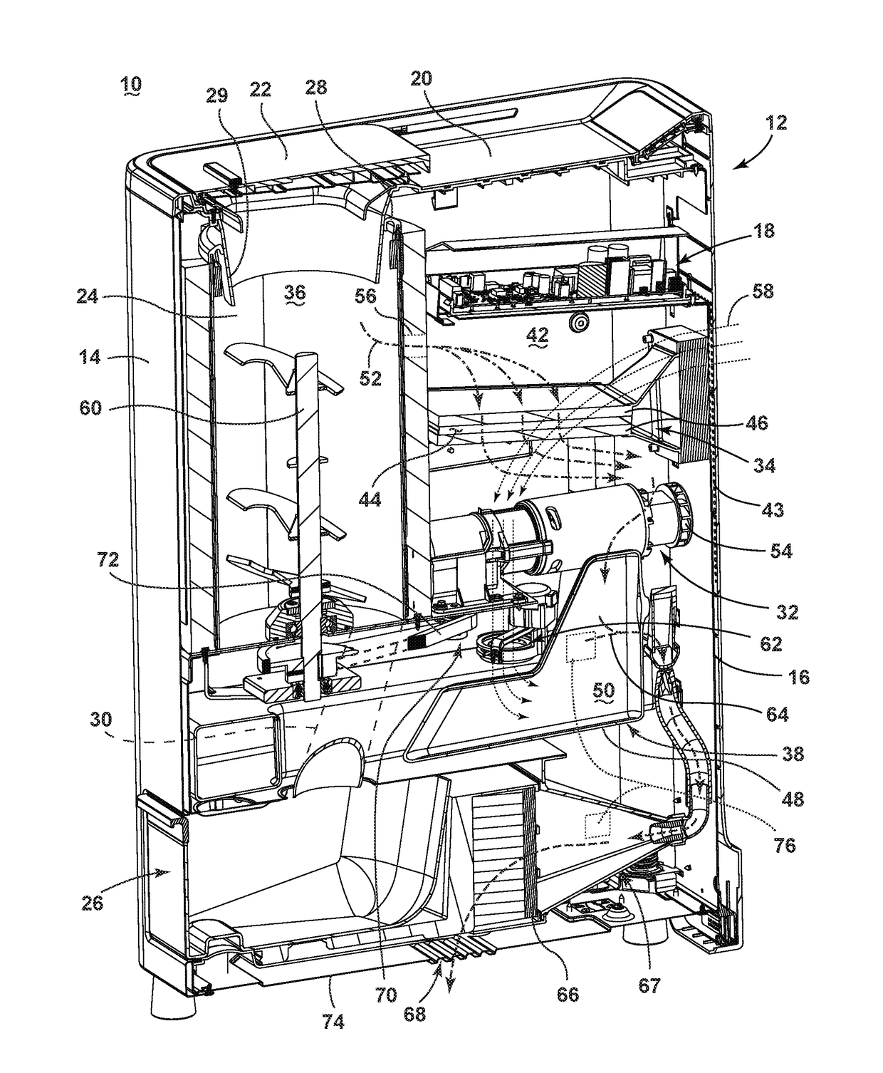
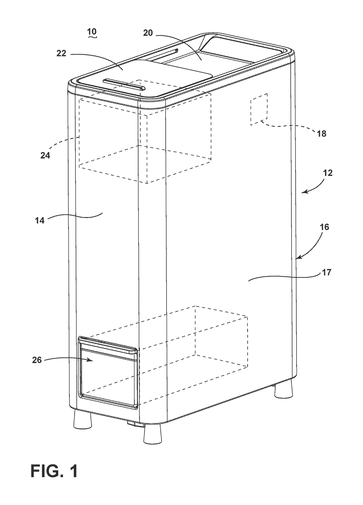
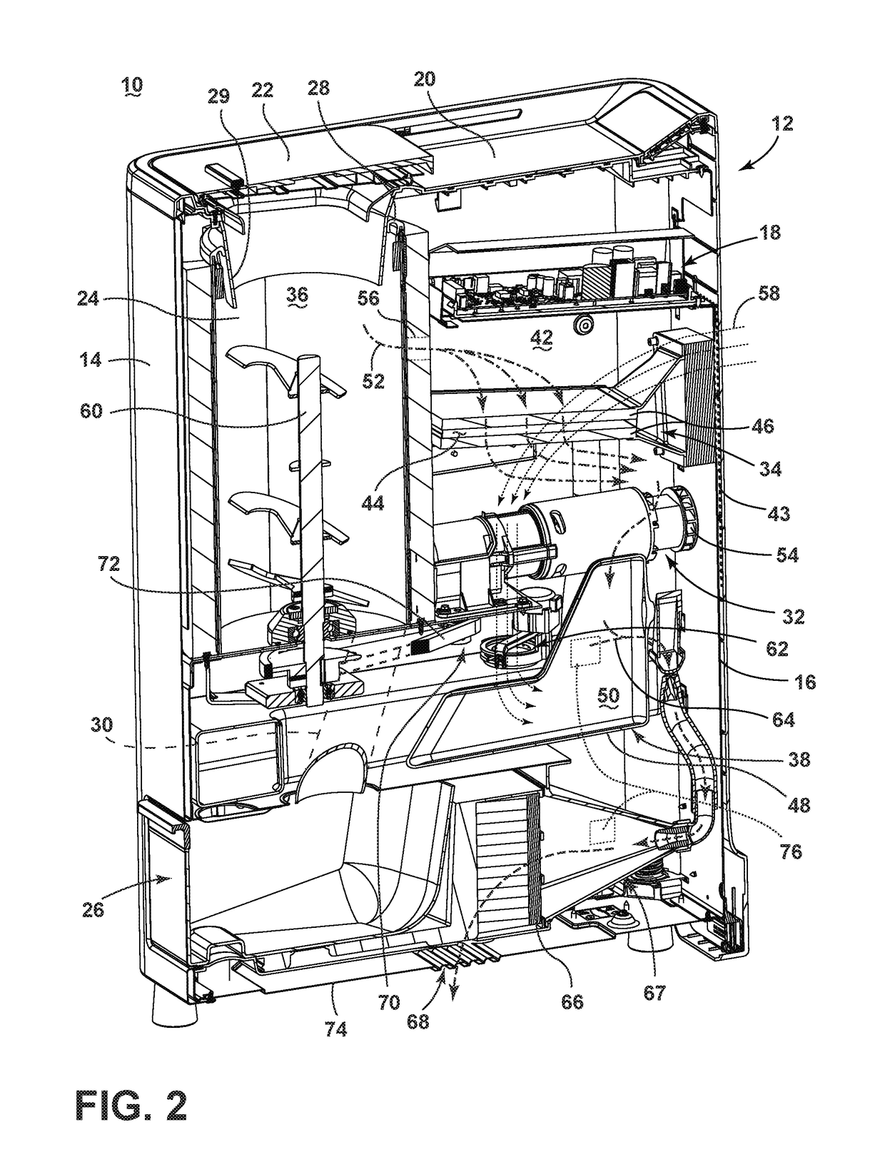
[0011]FIG. 1 illustrates a perspective view of a composting device 10 or composter for transforming organic material into compost by way of a composting cycle of operation. While a “composting device” or “composter” is described, embodiments of the invention can be equally applicable for similar devices, such as food recyclers or biological waste digesters. The composting device 10 can include a housing 12 having a front wall 14 spaced from a back wall 16, a pair of side walls 17, and a controller 18 located within the housing 12.

[0012]A top wall 20 can enclose the housing 12 at the top of the front wall 14, back wall 16, and the pair of side walls 17. The housing 12 can be any structure for enclosing, supporting and protecting the electrical and mechanical components of the composting device 10 including, but not limited to a cabinet and a frame.

[0013]The top wall 20 can include a cover 22 slidably mounted to a portion of the top wall 20 for sliding movement between open or closed ...


PUM

PropertyMeasurementUnit
temperatureaaaaaaaaaa

Abstract

A method and apparatus for operating a composter device includes a compost container, a condensate reservoir, a first fluid pathway fluidly coupling the composting chamber and the condensate reservoir, and a fan moving air from the composting chamber to the condensate reservoir along the first fluid pathway to define a first airflow.

Description

BACKGROUND[0001]Composting devices are known to implement a composting cycle for biologically and chemically decomposing organic material, such as food waste, into compost for use as a fertilizer and soil amendment. The composting cycle can be implemented in a composting bin by providing water, heat and aeration to the refuse, and can require a period of time for completion. Composting devices usually require a large floor space or a large volume for installation. Further, some composting devices can be a batch type device, therefore cannot be effective in producing compost in a continuous way.BRIEF SUMMARY[0002]In one aspect, a composter includes a compost container, a condensate reservoir, a first fluid pathway fluidly coupling the composting container and the condensate reservoir, a second fluid pathway coupling ambient air and the condensate reservoir and in heat transfer juxtaposition with the first fluid pathway, and a fan moving air from the composting chamber to the condensa...

Claims


Application Information

Patent Timeline
Patent Type & Authority Patents(United States)
IPC IPC(8): C12M1/00C05F17/02C12M3/00C05F17/00
CPCC05F17/027C05F17/0063C05F17/0205C05F17/0264C05F17/0282C05F17/60C05F17/907C05F17/971C05F17/979C05F17/993Y02W30/40Y02P20/145
Inventor MAGHAS, RACHELLATACK, THOMAS ALAN
Owner WHIRLPOOL CORP
Why Eureka
Try Eureka