Rotary seal for a central tire inflation system

a technology of central seals and tires, applied in the direction of tyre parts, tyre measurements, adjustable joints, etc., can solve the problems of complex manufacturing setup, and achieve the effect of convenient fluid communication, convenient fluid communication, and convenient fluid communication

Active Publication Date: 2018-07-03
DANA ITAL SPA
View PDF55 Cites 3 Cited by
  • Summary
  • Abstract
  • Description
  • Claims
  • Application Information

AI Technical Summary

Benefits of technology

[0009]In one embodiment, the present invention is directed to a rotary seal arrangement for use with a central tire inflation system. The rotary seal arrangement comprises a stationary portion, a rotating portion, a first sealing ring, a second sealing ring, and a first bushing. The stationary portion defines a first air passage therethrough. The rotating portion defines a second air passage therethrough. The first sealing ring is disposed on one of the rotating portion and the stationary portion. The second sealing ring is disposed on one of the rotating portion and the stationary portion. The first bushing is disposed on one of the rotating portion and the stationary portion. The first bushing is in dynamic sealing engagement with the first sealing ring. The stationary portion, the rotating portion, the first sealing ring, and the second sealing ring form a sealed cavity that facilitates fluid communication between the first air passage and the second air passage.
[0010]In another embodiment, the present invention is directed to a rotary seal arrangement for use with a central tire inflation system. The rotary seal arrangement comprises a stationary portion, a rotating portion, a first sealing ring, a second sealing ring, a first bushing, and a second bushing. The stationary portion defines a first air passage therethrough. The stationary portion includes an external ring disposed thereon and coupled thereto. The rotating portion defines a second air passage therethrough. The first sealing ring is disposed on the rotating portion. The second sealing ring is disposed on the external ring. The first bushing is disposed on the stationary portion. The first bushing is in dynamic sealing engagement with the first sealing ring. The second bushing is disposed on the rotating portion. The second bushing is in dynamic sealing engagement with the second sealing ring. The stationary portion, the rotating portion, the first sealing ring, and the second sealing ring form a sealed cavity that facilitates fluid communication between the first air passage and the second air passage.
[0011]In another embodiment, the present invention is directed to a rotary seal arrangement for use with a central tire inflation system. The rotary seal arrangement comprises a stationary assembly, a rotating portion, a first sealing ring, a second sealing ring, a first bushing, and a second bushing. The stationary assembly comprises a main portion, a radially extending portion, and a seal engaging portion. The stationary assembly defines a first air passage therethrough. The rotating portion defines a second air passage therethrough. The first sealing ring is disposed on the seal engaging portion. The second sealing ring is disposed on the seal engaging portion. The first bushing is disposed on the rotating portion. The first bushing is in dynamic sealing engagement with the first sealing ring. The second bushing is disposed on the rotating portion. The second bushing is in dynamic sealing engagement with the second sealing ring. The stationary portion, the rotating portion, the first sealing ring, and the second sealing ring form a sealed cavity that facilitates fluid communication between the first air passage and the second air passage.

Problems solved by technology

However, such a solution requires the design of the rotatable part to be integrated with the spindle and the wheel hub.
In some cases, this requires a complex manufacturing setup due to a length of the bores that have to be formed in the axle.

Method used


Image

  • Rotary seal for a central tire inflation system
  • Rotary seal for a central tire inflation system
  • Rotary seal for a central tire inflation system

Examples


Embodiment Construction

[0019]It is to be understood that the invention may assume various alternative orientations and step sequences, except where expressly specified to the contrary. It is also to be understood that the specific devices and processes illustrated in the attached drawings, and described in the following specification are simply exemplary embodiments of the inventive concepts of the present invention. Hence, specific dimensions, directions, orientations or other physical characteristics relating to the embodiments disclosed are not to be considered as limiting, unless expressly stated otherwise.

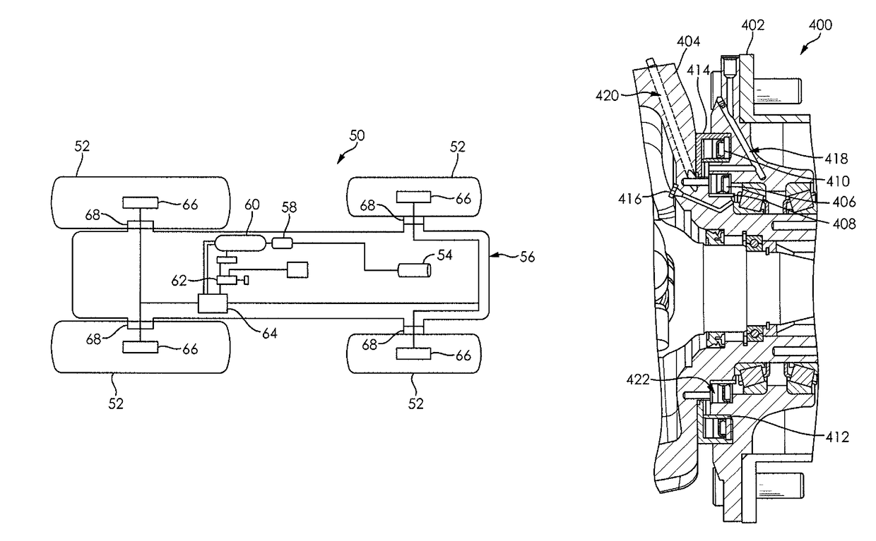
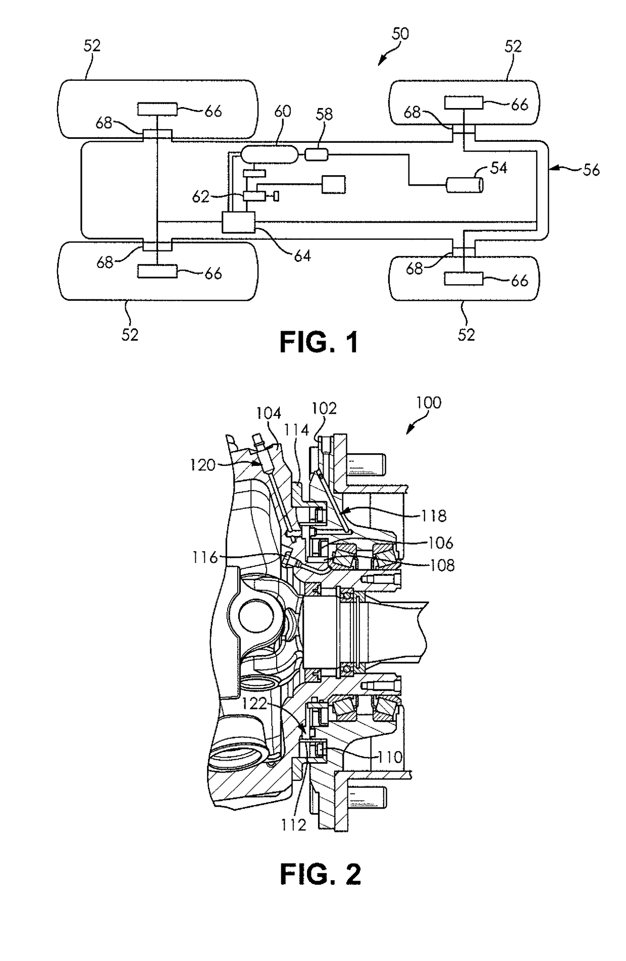
[0020]FIG. 2 illustrates a rotary seal arrangement 100 according to an embodiment of the invention. The rotary seal arrangement 100 comprises a rotating portion 102, a stationary portion 104, a first sealing ring 106, a first bushing 108, a second sealing ring 110, a second bushing 112, an external ring 114, and a breather 116. The first bushing 108 and the external ring 114 are disposed on the stat...


PUM


Abstract

A rotary seal arrangement for use with a central tire inflation system is provided. The rotary seal arrangement comprises a stationary portion, a rotating portion, a first sealing ring, a second sealing ring, and a first bushing portion. The stationary portion defines a first air passage therethrough and the rotating portion defines a second air passage therethrough. The first sealing ring and the second sealing ring are each disposed on one of the rotating portion and the stationary portion. The first bushing is disposed on one of the rotating portion and the stationary portion. The first bushing is in dynamic sealing engagement with the first sealing ring. The stationary portion, the rotating portion, the first sealing ring, and the second sealing ring form a sealed cavity that facilitates fluid communication between the first air passage and the second air passage.

Description

CLAIM OF PRIORITY[0001]The present application claims the benefit of priority to U.S. Provisional Application No. 62 / 020,111 filed on Jul. 2, 2014 and U.S. Provisional Application No. 62 / 073,537 filed on Oct. 31, 2014, both of which are incorporated herein in their entirety by reference.FIELD OF THE INVENTION[0002]The present invention relates to tire inflation systems and more specifically to tire inflation systems having rotary seals external to an axle.BACKGROUND OF THE INVENTION[0003]Tire inflation systems are becoming crucial in motor vehicles. Those systems are deeply adopted in different types of vehicles such as trucks, tractors or earth-moving machines. A main objective of a tire inflation system is to adapt the tire pressure to different operating conditions, which depends basically on the ground to be traveled as well as a speed and a load of a vehicle using the tire inflation system. A contact area of a tire is influenced by a pressure of the tire. With a low tire pressu...

Claims


Application Information

Patent Timeline
Patent Type & Authority Patents(United States)
IPC IPC(8): F16J15/34F16L27/08B60C23/00
CPCB60C23/003F16L27/0804F16J15/34B60C23/00363B60C23/00372B60C23/00345B60C23/00318B60C23/00
Inventor BONORA, MARIOCOSOLI, ETTORETONINI, DANIELE
Owner DANA ITAL SPA
Why Eureka
Try Eureka