Ophthalmic illumination profiles and associated devices, systems, and methods

a technology of ophthalmic illumination and profiles, applied in the field of ophthalmic illumination systems, can solve the problem of limited options for modifying the type of illumination within the eye, and achieve the effect of improving the quality of li

Active Publication Date: 2018-07-10
ALCON INC
View PDF17 Cites 23 Cited by
  • Summary
  • Abstract
  • Description
  • Claims
  • Application Information

AI Technical Summary

Benefits of technology

[0006]The presented solution fills an unmet medical need with a unique solution to output light having different angular profiles into the patient's eye during an ophthalmic surgical procedure. An illumination apparatus can include multiple optical fibers positioned within a cannula. The cannula can be inserted into the patient's eye. The optical fibers can be sized and shaped to respectively transmit light having different angular profiles. For example, one optical fiber can transmit light for wide-field illumination to provide general situational awareness for a surgeon during the surgical procedure. A second optical fiber can transmit light for narrow-field illumination. Narrow-field illumination can allow the surgeon to visualize anatomy within the patient's eye, such as vitreous humor. The surgeon can toggle between the multiple angular profiles of light depending the surgeon's visualization needs during the surgical procedure.

Problems solved by technology

Because endo-illuminators typically transmit wide-angle light, options for modifying the type of illumination within the eye can be limited.

Method used


Image

  • Ophthalmic illumination profiles and associated devices, systems, and methods
  • Ophthalmic illumination profiles and associated devices, systems, and methods
  • Ophthalmic illumination profiles and associated devices, systems, and methods

Examples


Embodiment Construction

[0020]In the following description, specific details can be set forth describing certain embodiments. It will be apparent, however, to one skilled in the art that the disclosed embodiments may be practiced without some or all of these specific details. Specific and / or illustrative, but not limiting, embodiments can be presented herein. One skilled in the art will realize that other material, although not specifically described herein, can be within the scope and spirit of this disclosure.

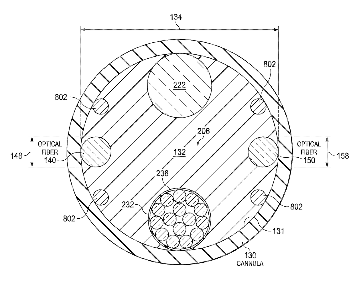
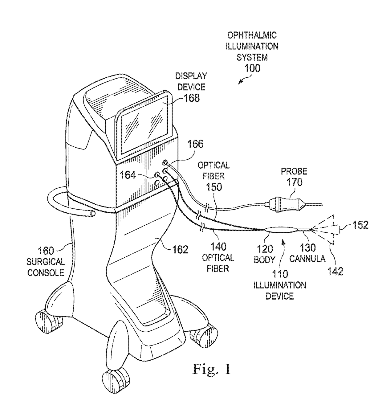
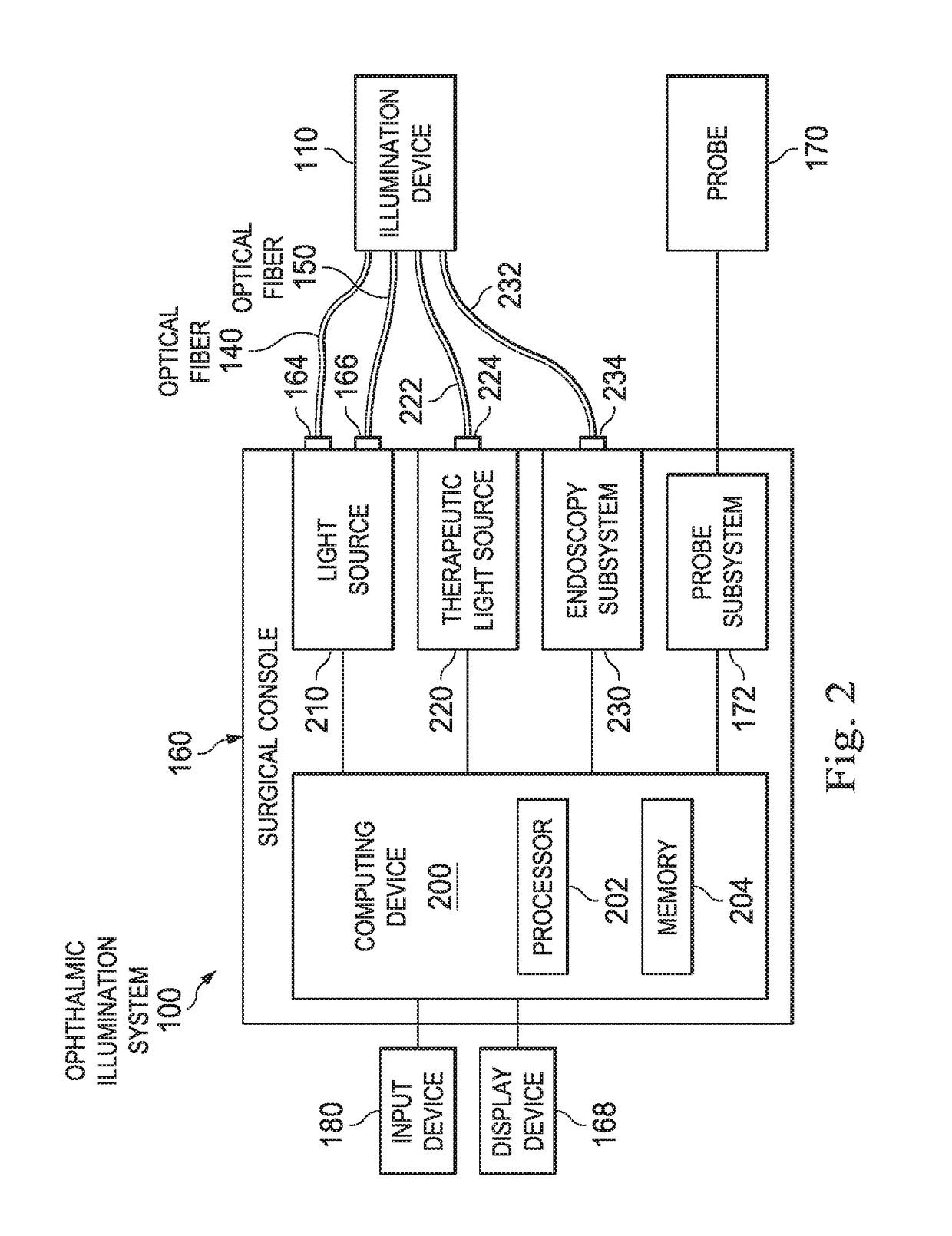
[0021]The present disclosure describes devices, systems, and methods of selectively illuminating a surgical field, such as a patient's eye, with light having different angular profiles. For example, a surgeon can choose to have wide-field, narrow-field, and / or other types of illumination during an ophthalmic surgical procedure. Two or more optical fibers can be positioned within a cannula of an ophthalmic illumination apparatus. The cannula can be inserted into the patient's eye. The optical fibers ...


PUM


Abstract

An ophthalmic illumination apparatus can include a body sized and shaped for grasping by a user. The apparatus can also include a cannula coupled to the body and configured to be positioned within an eye of a patient. The apparatus can further include a first optical fiber disposed within the cannula. The first optical fiber can be configured to transmit light having a first angular profile. The apparatus can also include a second optical fiber disposed within the cannula. The second optical fiber is configured to transmit light having a second angular profile. A method of surgical illumination can include illuminating an eye of a patient with light having a first angular profile. The method can also include illuminating the eye of the patient with light having a second angular profile. The different angular profiles can be transmitted by different optical fibers disposed within a cannula positioned within the eye.

Description

BACKGROUND[0001]Technical Field[0002]Embodiments disclosed herein can be related to ophthalmic illumination systems. More specifically, embodiments described herein can relate to illuminating a surgical field, such as a patient's eye, with light having different angular profiles transmitted by multiple optical fibers of an illumination device.[0003]Related Art[0004]Ophthalmic microsurgical procedures can require precision cutting and / or removing of various body tissues of the patient's eye. During a surgical procedure, a user, such as a surgeon or other medical professional, can hold an endo-illuminator or an endo-illumination probe in one hand. During a vitrectomy procedure, for example, the surgeon can hold a vitrectomy probe in his or her other hand. The vitrectomy probe can be used to perform surgical maneuvers while the surgeon visualizes the patient's eye using the light provided by the endo-illuminator. The endo-illuminator can include a cannula inserted into the eye and an o...

Claims


Application Information

Patent Timeline
Patent Type & Authority Patents(United States)
IPC IPC(8): A61B90/30A61B3/12A61F9/007A61F9/00
CPCA61B90/30A61B3/1225A61F9/0008A61F9/007A61B2090/306A61B3/0008
Inventor MIRSEPASSI, ALIREZAPAPAC, MICHAEL J.
Owner ALCON INC
Why Eureka
Try Eureka