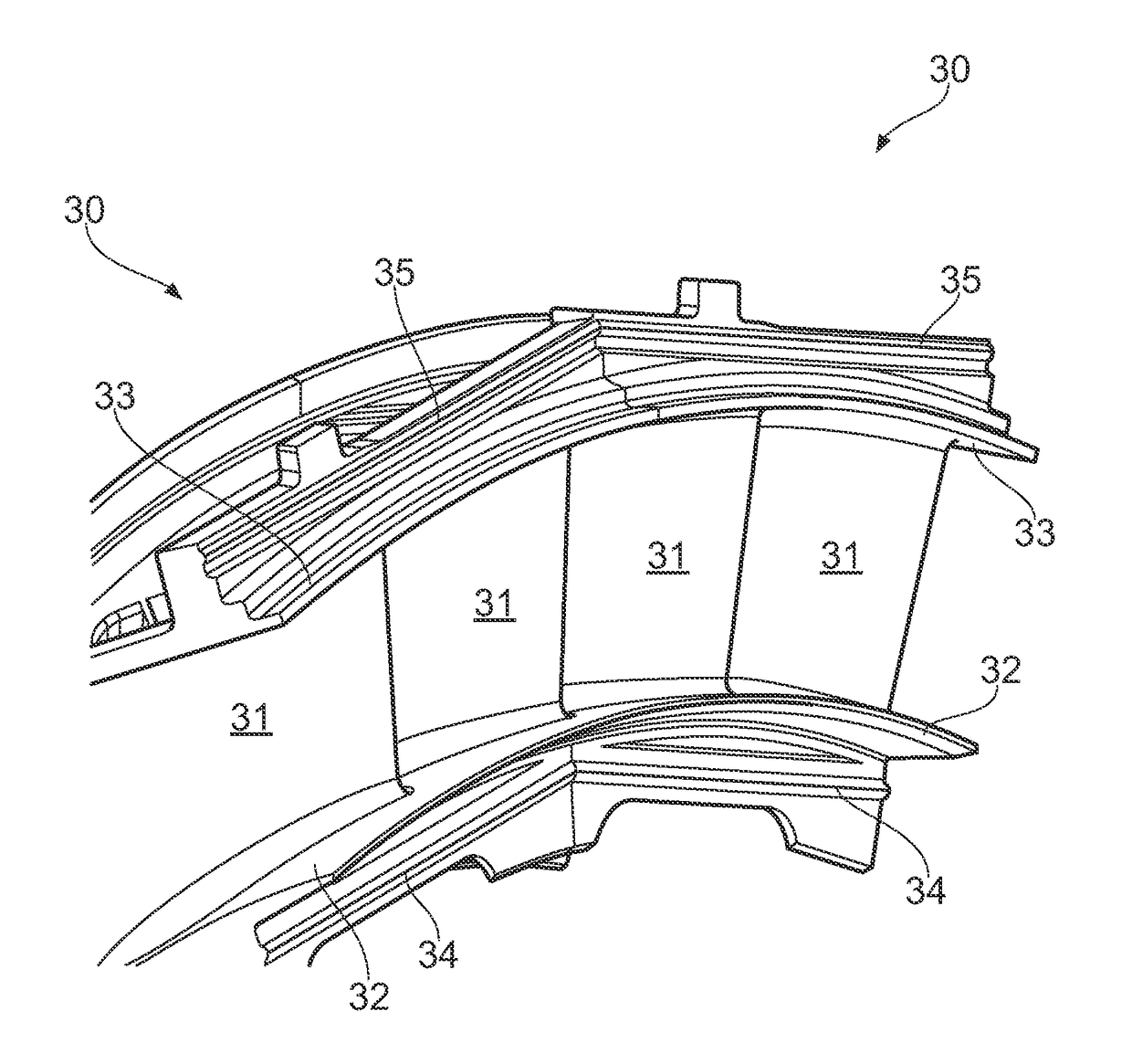
Method of designing guide vane formations

a technology of guide vane and formation, applied in the direction of stators, machines/engines, instruments, etc., can solve the problem of not being able to have chordal seals, etc., and achieve the effect of reducing or eliminating sawtooth leakage gaps

Active Publication Date: 2018-07-10
ROLLS ROYCE PLC
View PDF11 Cites 3 Cited by
  • Summary
  • Abstract
  • Description
  • Claims
  • Application Information

AI Technical Summary

Benefits of technology

[0010]The present invention is at least partly based on a realisation that it is possible to design guide vane formations in which the “saw-tooth” leakage gap can be eliminated for both the inner and outer polygons, even when the inner and outer chordal seals are axially offset from each other.
[0018](vii) defining, in the normal plane of a first one of the inner and outer chordal seals, (a) an arc of a circle which is centred on the engine centre line and contains the respective radial datum point, and (b) a tangent line to the arc such that the intersections of the tangent line with the wedge chock planes are at equal radial distances from the engine centre line, whereby the tangent line is the straight line of the first chordal seal, and whereby the straight line of the second chordal seal lies on the other normal plane, is parallel to the straight line of the first chordal seal and provides the radial height of the second chordal seal.
[0019]In this way, the contact lines of both the inner and outer chordal seal with their support rings can be made to link up in polygonal shapes with no “saw-tooth” leakage gaps. Substantial engine efficiency improvements (e.g. of the order of −0.1% of specific fuel consumption) can thus be obtained. In particular, the method allows the elimination of the “saw-tooth” leakage gaps even when the inner and outer chordal seals are axially offset from each other (i.e. the normal planes are axially offset from each other).
[0025]In the second aspect, the platform side faces and chordal seals are designed before the guide vane formation is formed. However, an alternative approach is to start with a guide vane formation which is partially manufactured, and then to finish the guide vane formation using the approach of the present invention. In particular, a partially manufactured guide vane formation may already have radially inner and outer platforms, one or more aerofoil bodies, and inner and outer chordal seals, but the inner and outer platforms may be oversized in the circumferential direction, meaning their side faces are at provisional positions and there is still an opportunity to finish machine them to final positions. This opportunity can be used to reduce or eliminate sawtooth leakage gaps in existing engine designs where parameters such as the positions of the chordal seals cannot be altered.
[0031](v) rotating the segment planes about the engine centre line, the rotation preserving the angle between the segment planes, in order to adjust the positions of the wedge chock planes and the corresponding final positions of the side faces such that sawtooth leakage gaps of the inner and outer chordal seals are reduced or eliminated; and

Problems solved by technology

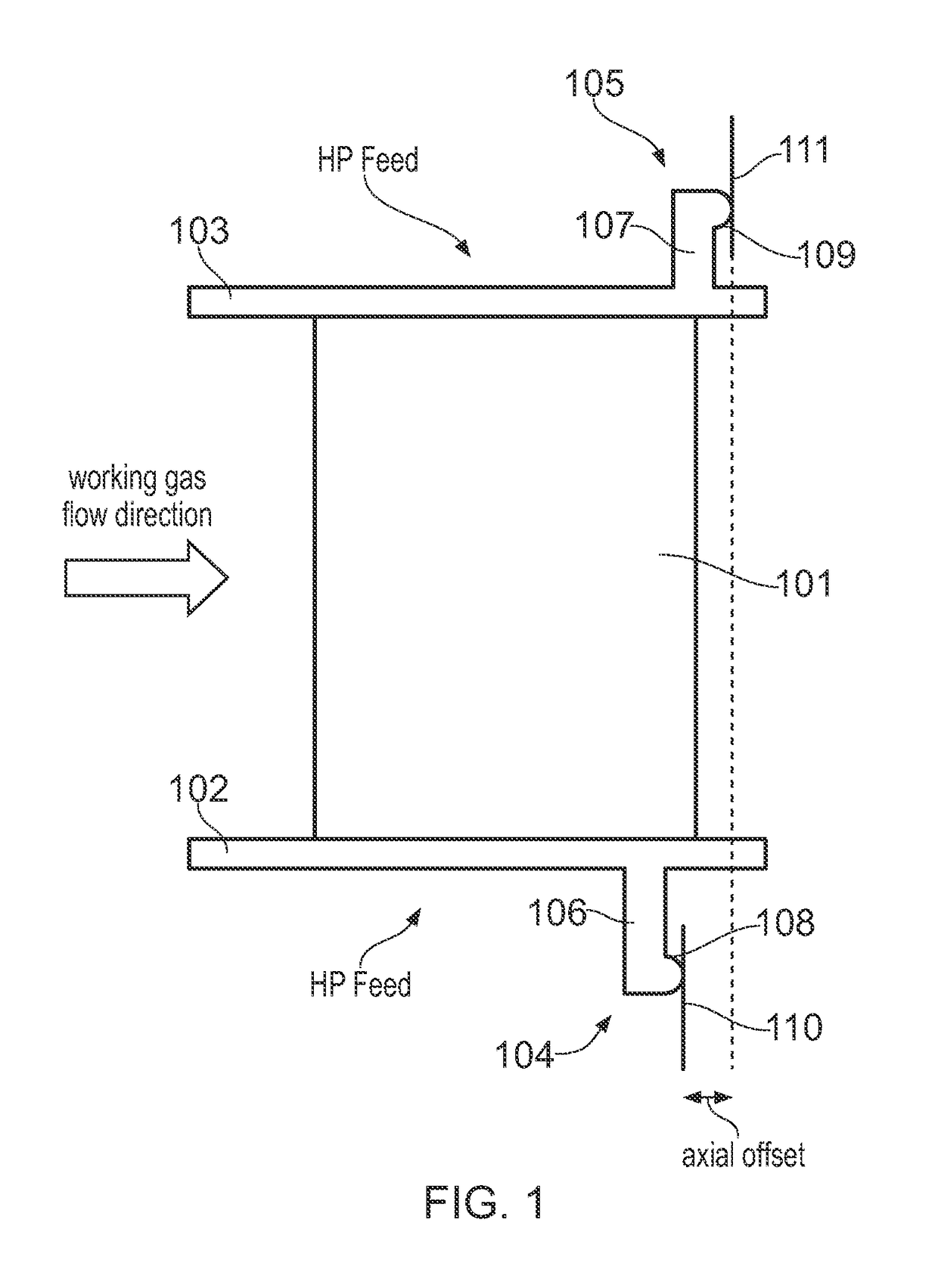
However, due to engine design constraints, it is often not possible to have the chordal seals 104, 105 in the same axial position.
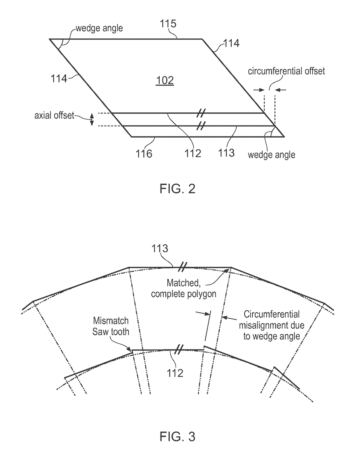
Typically, however, such linking up is only achieved for at most one of the inner and outer polygons, and “saw-tooth” leakage gaps result at the ends of the chordal seals of the other polygon as a result of the circumferential offset, as shown in FIG. 3.
The leakage through this “saw-tooth” gap can be extremely penalising to turbine efficiency due the large pressure differential across the seal.

Method used


Image

  • Method of designing guide vane formations
  • Method of designing guide vane formations
  • Method of designing guide vane formations

Examples


Embodiment Construction

[0062]With reference to FIG. 4, a ducted fan gas turbine engine incorporating the invention is generally indicated at 10 and has a principal and rotational axis X-X. The engine comprises, in axial flow series, an air intake 11, a propulsive fan 12, an intermediate pressure compressor 13, a high-pressure compressor 14, combustion equipment 15, a high-pressure turbine 16, an intermediate pressure turbine 17, a low-pressure turbine 18 and a core engine exhaust nozzle 19. A nacelle 21 generally surrounds the engine 10 and defines the intake 11, a bypass duct 22 and a bypass exhaust nozzle 23.

[0063]During operation, air entering the intake 11 is accelerated by the fan 12 to produce two air flows: a first air flow A into the intermediate pressure compressor 13 and a second air flow B which passes through the bypass duct 22 to provide propulsive thrust. The intermediate pressure compressor 13 compresses the air flow A directed into it before delivering that air to the high pressure compres...


PUM


Abstract

A computer-based method of designing a guide vane formation is provided. The vane formation is for use in a gas turbine engine which has a cascade of circumferentially arranged identical guide vane formations. The vane formation has radially inner and radially outer chordal seals. The method allows the elimination of “saw-tooth” leakage gaps between inner chordal seals of neighboring vane formations and between outer chordal seals of neighboring vane formations even when the inner and outer chordal seals are axially offset from each other.

Description

FIELD OF THE INVENTION[0001]The present invention relates to a method of designing guide vane formations, such as gas turbine engine nozzle guide vane formations.BACKGROUND OF THE INVENTION[0002]Control of fluid flows through a gas turbine engine is important to achieve efficiency and performance. Guide vanes are utilised in order to direct and present gas flows generated by the compressor and turbine stages of an engine. These vanes generally act between the stages of the engine. For example, a cascade of high-pressure turbine (HPT) nozzle guide vanes (NGVs) directs and guides the working gas flow from the combustor to the high pressure turbine.[0003]FIG. 1 shows schematically a side view of an HPT NGV formation. The NGV formation has one or more aerofoil bodies 101 which span the working gas annulus of the engine, the direction of flow of the working gas being indicated. At radially inner and outer ends of the aerofoil bodies, the vane formation has respectively inner 102 and oute...

Claims


Application Information

Patent Timeline
Patent Type & Authority Patents(United States)
IPC IPC(8): F01D9/04G06F17/50
CPCF01D9/041G06F17/5086F05D2240/129F05D2230/10F05D2220/32G06F30/17
Inventor HELVACI, CANER HASANCOOPER, BRIAN GUY
Owner ROLLS ROYCE PLC
Why Eureka
Try Eureka