

Dither mask generation method and device
a mask generation and halftone technology, applied in the field of dither mask generation methods and devices, can solve the problem of easy generation of stripes in halftone images
- Summary
- Abstract
- Description
- Claims
- Application Information
AI Technical Summary
Benefits of technology
Problems solved by technology
Method used
Image

Examples
second embodiment
[0297]The second embodiment which is a modification of the first embodiment described above is described.
[0298]FIG. 30 is a flowchart illustrating an example of ascending order threshold setting processing by the second embodiment. Instead of the flowchart described in FIG. 21, the flowchart illustrated in FIG. 30 can be applied. In FIG. 30, the same step numbers are attached to the processes that are the same as or similar to that in the flowchart described in FIG. 21, and the description is omitted.
[0299]In the example illustrated in FIG. 30, as a setting method of the thresholds after setting the dot priority pixels, a technique of a void-and-cluster method is used. The void-and-cluster method is described, for example, in Robert A. Ulichney “Void-and-cluster method for dither array generation”, Proc. SPIE 1913, Human Vision, Visual Processing, and Digital Display IV, 332 (Sep. 8, 1993).
[0300]In the flowchart in FIG. 30, the setting of the dot priority pixels and the technique of...
third embodiment
[0309]FIG. 31 is a flowchart illustrating a procedure of a dither mask generation method relating to the third embodiment. In the flowchart in FIG. 31, the same step numbers are attached to the processes that are the same as or similar to that in the flowchart described in FIG. 21.
[0310]In the dither mask generation method illustrated in FIG. 31, the nozzle relative ejection rates of the individual nozzle numbers in the recording head are set first (step S14). The process in step S14 corresponds to one form of “nozzle relative ejection rate setting process”.
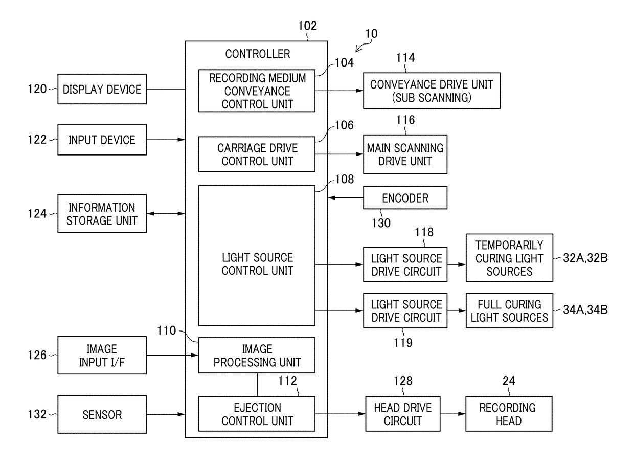
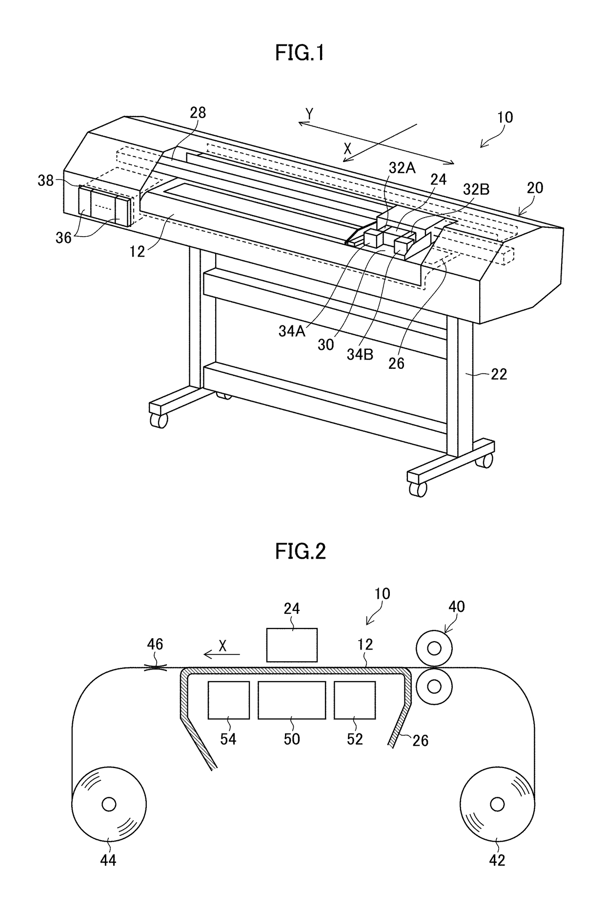
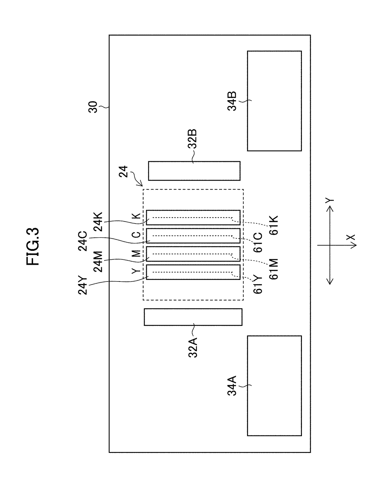
[0311]Next, for the image area (that is, the mask area) having the pixel array with the number of pixels equal to the mask size of the dither mask, the nozzle numbers (that is the nozzle pattern) corresponding to the individual pixels of the dither mask are set according to the scanning pattern when the image recording by the inkjet recording device 10 is performed (step S16). The process in step S16 corresponds to one form of “n...
fourth embodiment
[0407]In the dither mask generation method described in the third embodiment, a huge operation amount is required since it is needed, as described in FIG. 33, FIG. 36 and FIG. 37, to repeatedly execute the processing of temporarily setting the target pixel to the threshold non-set pixel to be a candidate every time of setting the individual thresholds, temporarily placing the dot to the first dot arrangement and adding the second low-pass filter to the low-pass dot arrangement image in the case of an ascending threshold setting order, temporarily removing the dot from the first dot arrangement and removing the second low-pass filter from the low-pass dot arrangement image in the case of a descending threshold setting order, and calculating the error between the low-pass ejection rate reflecting input image and the low-pass dot arrangement image.
[0408]Therefore, in the fourth embodiment, a device capable of generating the dither mask with an operation amount smaller than that in the ...
PUM
 Abstract
Description
Claims
Application Information