
System and method to detect anomalies

a technology of anomalies and detection methods, applied in the field of anomaly detection, can solve the problems of not having spectroscopic capabilities, unable to analyze the chemical composition of articles, and health risks of operators of such systems, and achieve the effects of minimal equipment footprint, ease of use, and minimal staffing

Active Publication Date: 2018-07-17
LUNA INNOVATIONS
View PDF23 Cites 1 Cited by
  • Summary
  • Abstract
  • Description
  • Claims
  • Application Information

AI Technical Summary

Benefits of technology

[0012]There are up to three primary functional requirements that compose the system and method capability: (1) detect anomalies in the head-region possibly concealed by clothing on or off the body; and in particular religious headwear, wigs, hats, caps or scarves—other uses would be to detect anomalies in casts and prosthesis; (2) allow a single screening officer to provide targeted screening of a passenger with minimal equipment footprint, minimal staffing, ease-of-use, and potential portability for screening in areas other than the checkpoint; and (3) perform detection while not tied to an image or image interpretation.

Problems solved by technology

However, CT systems emit X-rays, which may pose a health risk to the operators of such systems, as well as passengers who may be standing near the system, and hence CT systems generally include some type of shield to protect the operators and passengers ionizing radiation.
Moreover, although CT systems are capable of analyzing the density of an article, along with other characteristics of the shape and volume of the article, these systems do not have spectroscopic capabilities, and therefore cannot analyze the chemical compositions of the articles.
Furthermore, X-rays are not sensitive to the optical traits that result from the article's refractive index and absorption coefficient.

Method used


Image

  • System and method to detect anomalies
  • System and method to detect anomalies
  • System and method to detect anomalies

Examples


Embodiment Construction

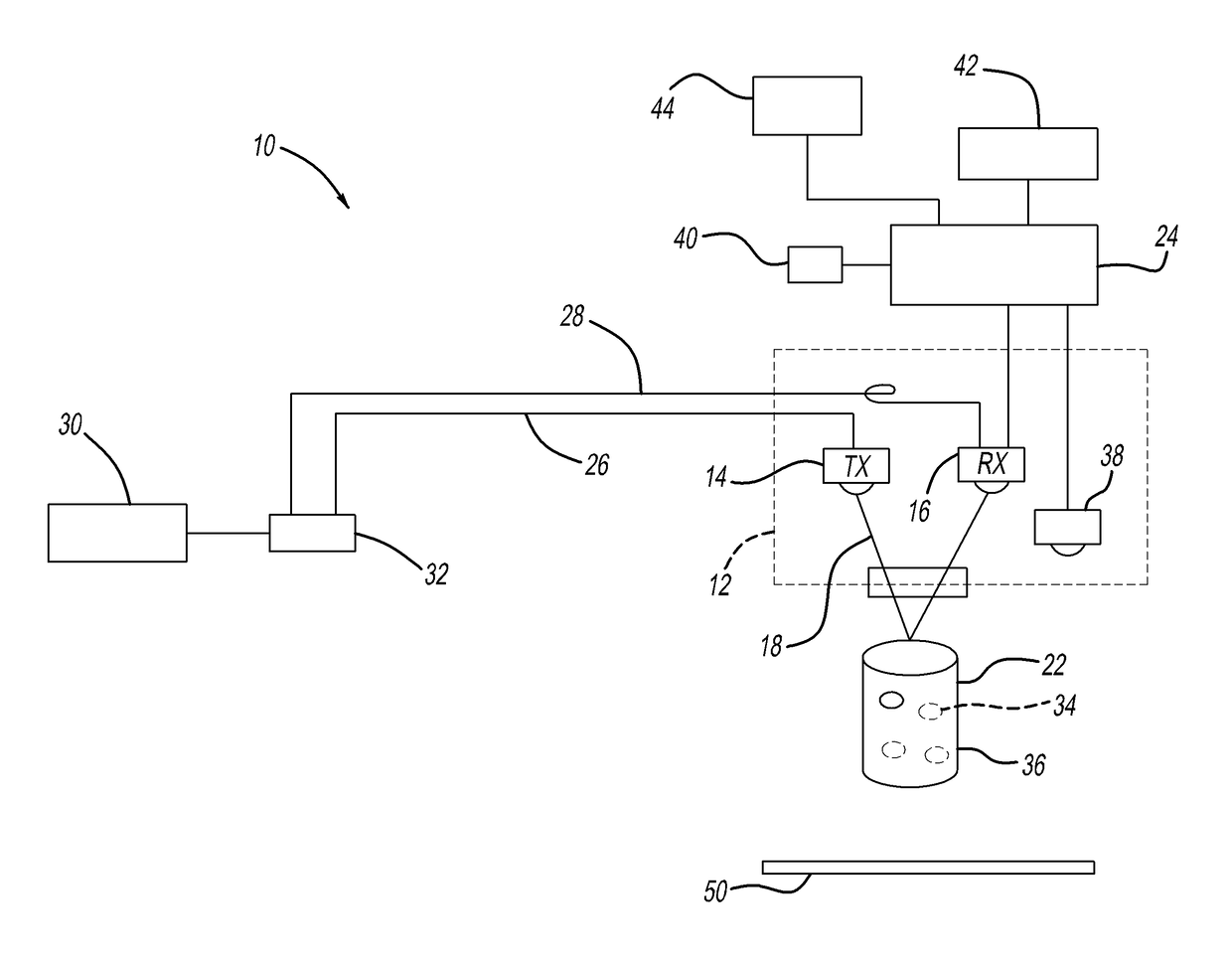
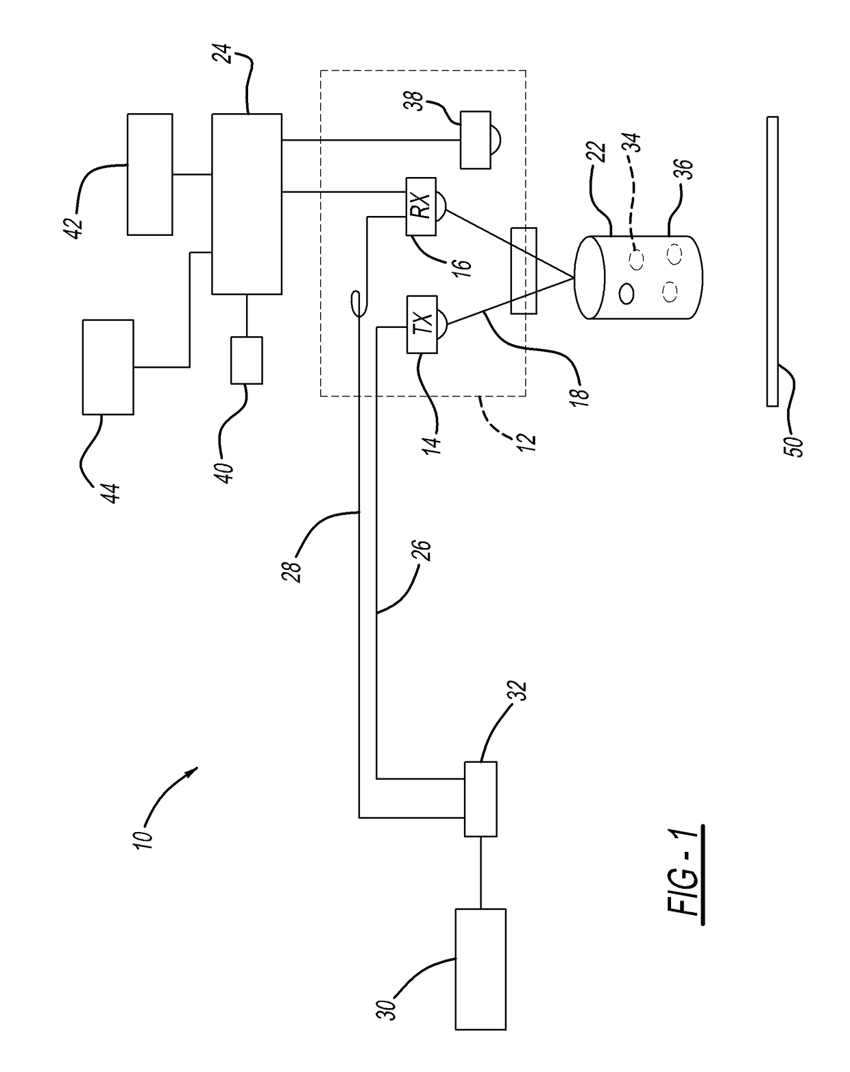
[0038]Referring to FIG. 1, the system 10 includes a detection probe 12 having an electromagnetic transmitter 14 and an electromagnetic receiver 16. The electromagnetic transmitter 14 is configured to emit electromagnetic pulses 18, while the electromagnetic receiver 16 is configured to sample electromagnetic pulses 18 from the electromagnetic receiver 14 at specified times within a waveform window. The electromagnetic pulses 18 may span the terahertz spectral region of 0.04 to 4 THz.

[0039]The system further includes an objective optic 20 incorporated in the detection probe 12 for directing the pulsed electromagnetic radiation 18 through a concealment stack 22 and collecting reflections 18 of the concealment stack 22 at a defined distance, wherein the detection probe 12 may be focused at the depth of concealed skin of the person without the exterior of the detection probe 12 contacting a top of the concealment stack 22. The transmitter 14 and receiver 16 may be configured in a monost...


PUM


Abstract

A system and method for detecting anomalies concealed upon a person may include a detection probe having an electromagnetic transmitter and an electromagnetic receiver. The electromagnetic transmitter is configured to emit electromagnetic pulses, while the electromagnetic receiver is configured to sample electromagnetic pulses from the electromagnetic receiver at specified times within a waveform window. The electromagnetic pulses may span the terahertz spectral region of 0.04 to 4 THz. The system may also have optical fibers connected to the electromagnetic transmitter and electromagnetic receiver, wherein femtosecond laser pulses are directed from a source to the electromagnetic transmitter and the electromagnetic receiver by the optical fibers.

Description

CROSS REFERENCE TO RELATED APPLICATIONS[0001]This application is a nationalization of PCT Serial No. PCT / US2013 / 033650, filed Mar. 25, 2013 which claims benefit of U.S. Provisional Application Ser. No. 61 / 614,903, filed Mar. 23, 2012.BACKGROUND[0002]1. Field of the Invention[0003]The system and method relates to anomaly detection for detecting anomalous objects on the body of a person.[0004]2. Description of the Known Art[0005]Computerized tomography (“CT”) imaging has been employed for non-destructive examination of various types of articles, such as contraband, which may be hidden inside luggage. However, CT systems emit X-rays, which may pose a health risk to the operators of such systems, as well as passengers who may be standing near the system, and hence CT systems generally include some type of shield to protect the operators and passengers ionizing radiation. Moreover, although CT systems are capable of analyzing the density of an article, along with other characteristics of...

Claims


Application Information

Patent Timeline
Patent Type & Authority Patents(United States)
IPC IPC(8): G01S17/02G01V5/00G01S17/88G01S13/02G01S13/88G01S7/41G01S7/48G01S17/00G01S17/10G01S13/00G01S13/10G01S17/04
CPCG01S17/026G01S7/412G01S7/4802G01S13/0209G01S13/887G01V5/0016G01S17/88G01S17/10G01S13/003G01S13/10G01S17/003G01V3/12G01V11/00G01S17/04
Inventor ZIMDARS, DAVID
Owner LUNA INNOVATIONS
Learn More