Injection locked phase locked loop
- Summary
- Abstract
- Description
- Claims
- Application Information
AI Technical Summary
Benefits of technology
Problems solved by technology
Method used
Image

Examples
Embodiment Construction
[0019]Hereafter, various embodiments will be described below in more detail with reference to the accompanying drawings.
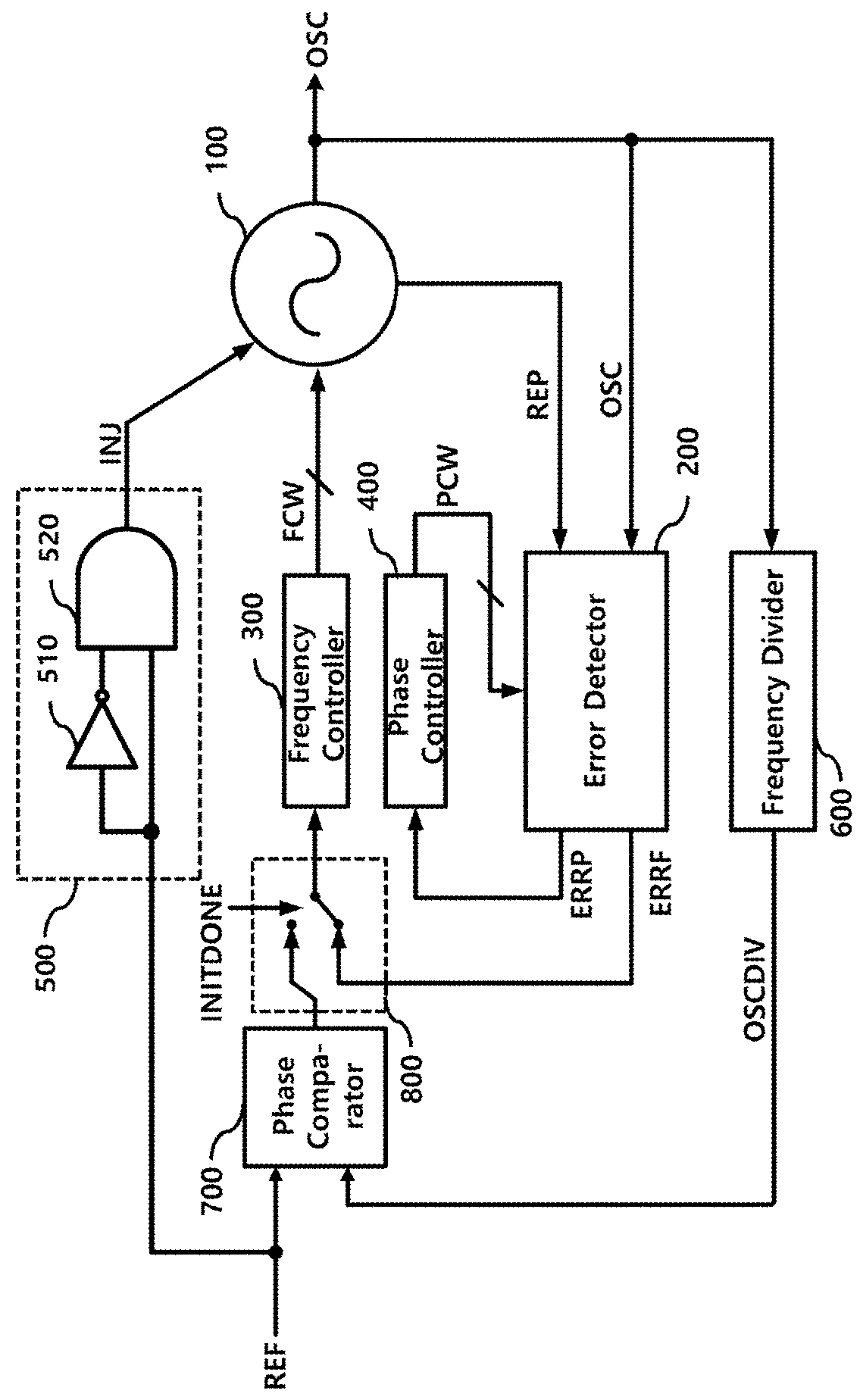
[0020]FIG. 1 is a block diagram of an injection locked phase locked loop 10 according to an embodiment of the present disclosure.
[0021]In the embodiment of FIG. 1, the injection locked phase locked loop includes an injection locked oscillator 100, an error detector 200, a frequency controller 300, a phase controller 400, and an injection signal generator 500.
[0022]In the embodiment of FIG. 1, the injection locked phase locked loop 10 may further include a frequency divider 600, a phase comparator 700, and a path selector 800.
[0023]The injection signal generator 500 outputs a pulse injection signal (or an injection signal) INJ synchronized with an edge (e.g., a rising edge) of a reference clock signal REF.
[0024]The injection signal generator 500 includes an inversion delay circuit 510 for inverting and delaying the reference clock signal REF and a logic gate (e.g., ...
PUM
 Abstract
Description
Claims
Application Information