Conditioning module for regulating the temperature of and humidifying a flowing gas

a technology of conditioned gas and temperature regulation, which is applied in the direction of respirators, lighting and heating apparatus, heating types, etc., can solve the problems of only increasing the amount of conditioned volume flow, reducing the temperature of the gas, and developing high flow resistance for the gas, so as to achieve the lowest possible flow resistance, the smallest possible total gas volume, and the effect of simple and favorable manner

Active Publication Date: 2018-08-14
DRAGER SAFETY
View PDF10 Cites 0 Cited by
  • Summary
  • Abstract
  • Description
  • Claims
  • Application Information

AI Technical Summary

Benefits of technology

[0006]Based on this state of the art, a basic object of the present invention is to eliminate these drawbacks at least partially in conditioning modules. Therefore, an object of the present invention is to provide a conditioning module, which generates a large volume flow of temperature-regulated and humidified gas in an especially simple and favorable manner and which especially has at the same time the smallest possible total gas volume as well as the lowest possible flow resistance.

Problems solved by technology

It is, however, disadvantageous here that a high flow resistance develops for the gas due to the use of the thin tubes.
It is, however, disadvantageous here that the temperature regulation and humidification of only a small volume flow of gas can be achieved.
An increase in the amount of conditioned volume flow can only be achieved by enlarging the entire device in this case as well.
Providing larger volume flows, which are likewise often necessary according to the specifications, solely by a corresponding scale-up of the device used thus has limitations, at least in this field of use.

Method used


Image

  • Conditioning module for regulating the temperature of and humidifying a flowing gas
  • Conditioning module for regulating the temperature of and humidifying a flowing gas
  • Conditioning module for regulating the temperature of and humidifying a flowing gas

Examples


Embodiment Construction

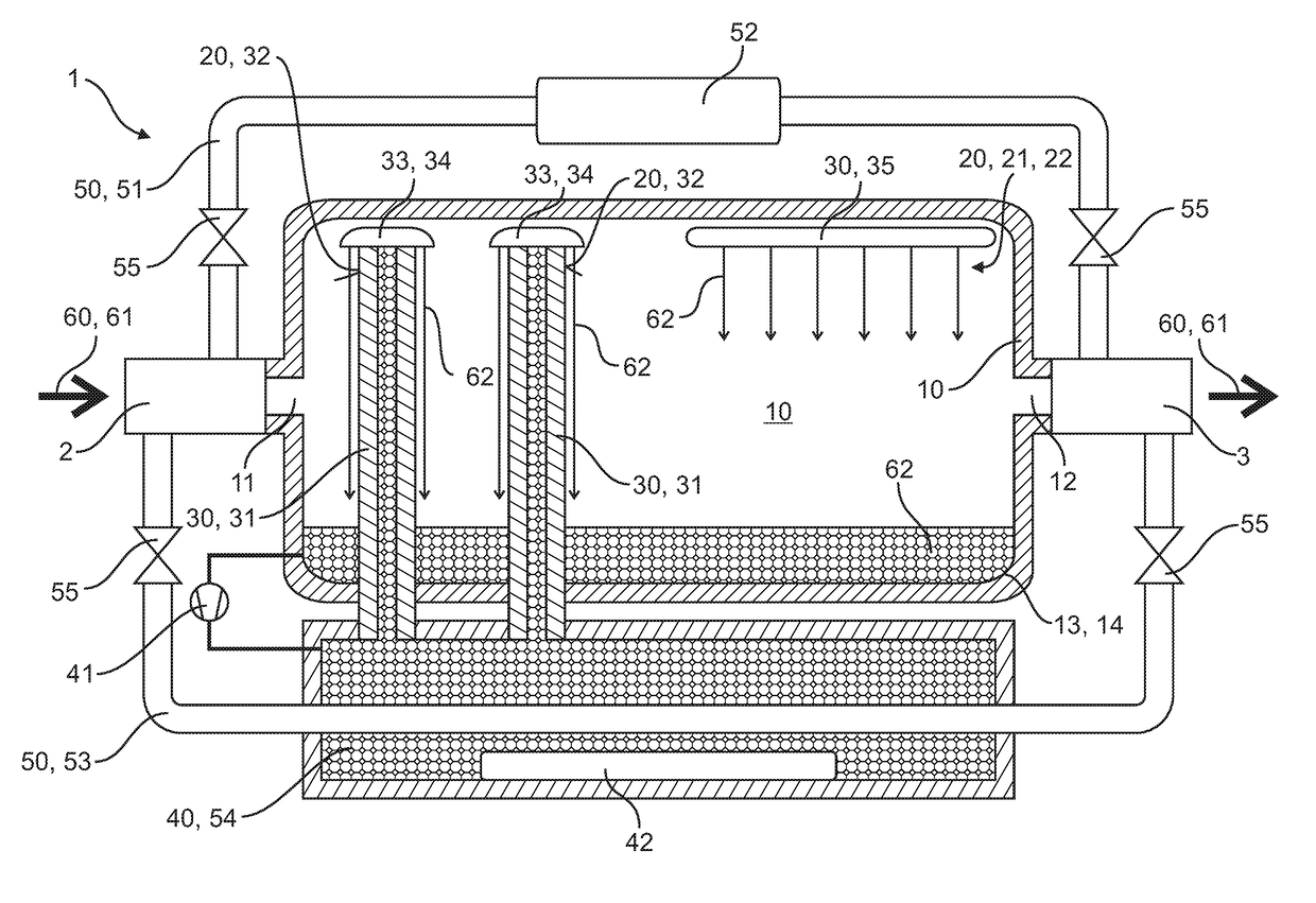
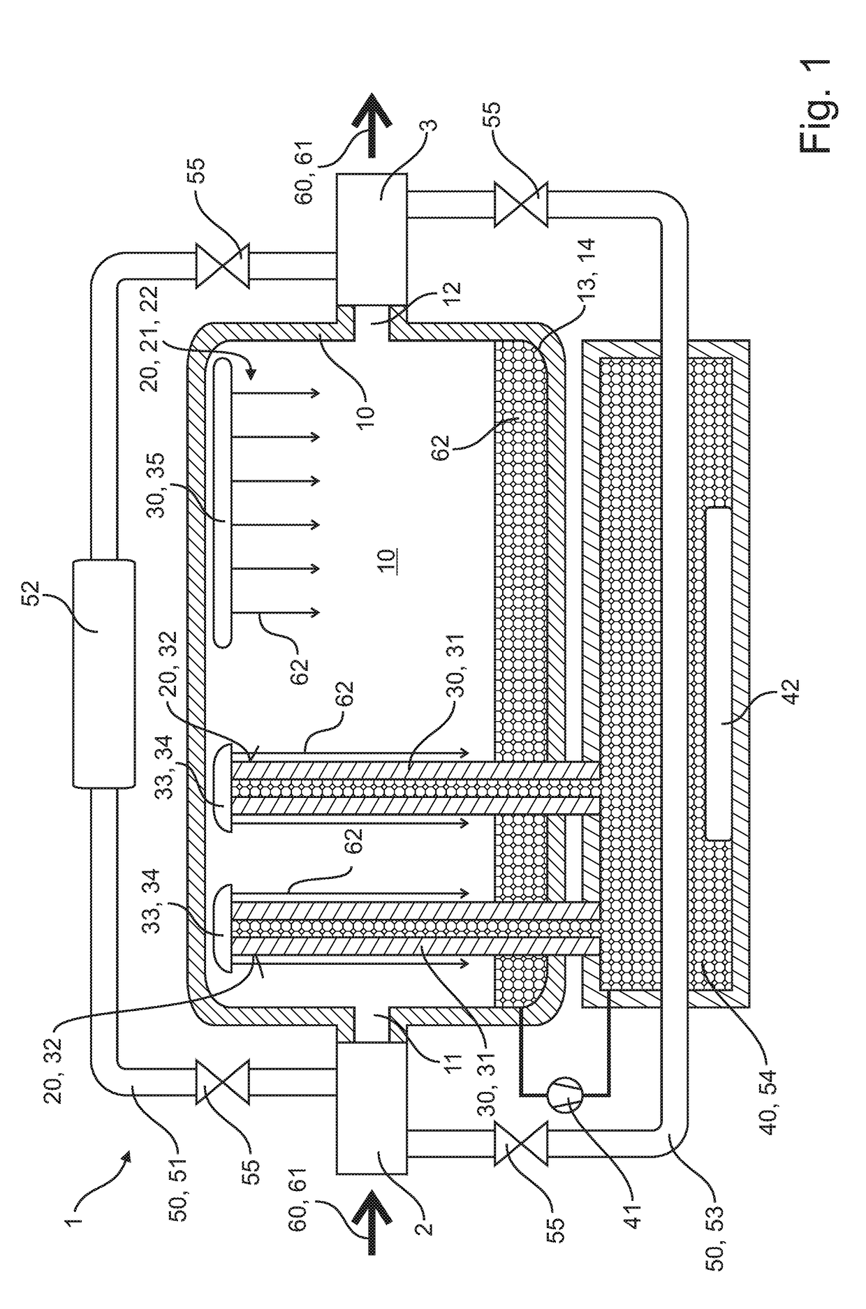
[0029]Referring to the drawings, FIG. 1 shows a conditioning module 1 according to the present invention with a flowthrough body 10. A gas 60, especially air 61, can be humidified and its temperature can be regulated in the conditioning module 1. For this, the flowthrough body 10 has an inflow opening 11, which is connected to a gas feed line 2 in a fluid-communicating manner. The gas 60 flows through the inflow opening 11 into the flowthrough body 10 and is humidified and a temperature of the gas is regulated in the interior of the flowthrough body 10 and then the gas flows out of the flowthrough body 10 through an outflow opening 12, which is connected to a gas outflow line 3 in a fluid-communicating manner. A plurality of delivery devices 30, which are configured for wetting an inner wall area 20 of the flowthrough body 10, are arranged in the interior of the flowthrough body 10, which is configured as a hollow body. The individual delivery devices 30 are shown schematically and ...


PUM

PropertyMeasurementUnit
angleaaaaaaaaaa
temperatureaaaaaaaaaa

Abstract

A conditioning module (1), for regulating the temperature of and humidifying a flowing gas (60), has a flowthrough body (10) with an inflow opening (11) and with an outflow opening (12). The inflow opening (11) is connected to a gas feed line (2) in a fluid-communicating manner and the outflow opening (12) is connected to a gas outflow line (3) in a fluid-communicating manner. A lower inner area (13) of the flowthrough body (10) is configured as a collecting tank (14) for collecting water (62).

Description

CROSS REFERENCE TO RELATED APPLICATIONS[0001]This application claims the benefit of priority under 35 U.S.C. § 119 of German Application 10 2015 012 783.7 filed Oct. 5, 2015, the entire contents of which are incorporated herein by reference.FIELD OF THE INVENTION[0002]The present invention pertains to a conditioning module for regulating the temperature of and humidifying a flowing gas, having a flowthrough body with an inflow opening and with an outflow opening, wherein the flow opening is connected to a gas feed line in a fluid-communicating manner and the outflow opening is connected to a gas outflow opening in a fluid-communicating manner, and wherein a lower inner area of the flowthrough body is configured as a collecting tank for collecting water.BACKGROUND OF THE INVENTION[0003]Devices for simulating pulmonary activities and / or pulmonary functions are known, in principle, in modern technology. Such lung simulators, which can provide especially a sinusoidal motion of air, i.e....

Claims


Application Information

Patent Timeline
Patent Type & Authority Patents(United States)
IPC IPC(8): B01F3/04A61M16/16A61M16/10B01F15/06B01F5/06A61M16/00
CPCB01F3/04007A61M16/108A61M16/109A61M16/16B01F3/04049B01F5/06B01F15/065A61M16/0003B01F2015/062A61M2205/3368A61M2205/3606A61M2205/366A61M2205/70A61M2209/02B01F2015/061F24F3/14F24F5/0003F24F13/00F24F2221/34B01F23/21B01F23/2132B01F25/40B01F35/92B01F2035/98B01F2035/99
Inventor HENF, DIRK
Owner DRAGER SAFETY
Why Eureka
Try Eureka