
Phonon generation in bulk material for manufacturing

Active Publication Date: 2018-09-04
CHEVRON PHILLIPS CHEMICAL CO LP
View PDF17 Cites 67 Cited by
  • Summary
  • Abstract
  • Description
  • Claims
  • Application Information

AI Technical Summary

Benefits of technology

The present patent text discusses methods for producing articles of manufacture using controlled emissions to generate patterns of excitation within a substrate. The techniques described allow for the production of articles with speed and efficiency, similar to how 3D printing works but on a commercial scale. The process involves depositing a manufacturing material on a substrate and causing the material to combine with the substrate in a layer-by-layer process. The substrate may be the same or different than the manufacturing material. The techniques described allow for the production of articles that meet the requirements of settings where speed and efficiency are important.

Problems solved by technology

Unfortunately, the specialized equipment that is used to produce these articles of manufacture on a large scale generally represent a very large capital investment on the part of the manufacturer.
Rather, such articles must be packaged and transported to a customer, which may use the articles as-is, or may subject them to further manufacturing processes.
While capable of producing three-dimensional constructs, 3D printing processes generally take several hours to complete.
Accordingly, while capable of producing unique items, such techniques do not generally have the capability to meet the requirements of settings in which an item may be desired within a few minutes, rather than a few hours.
This relatively low throughput has limited the acceptance of 3D printing as a viable commercial technique for producing consumer goods.

Method used


Image

  • Phonon generation in bulk material for manufacturing
  • Phonon generation in bulk material for manufacturing
  • Phonon generation in bulk material for manufacturing

Examples


embodiment 1

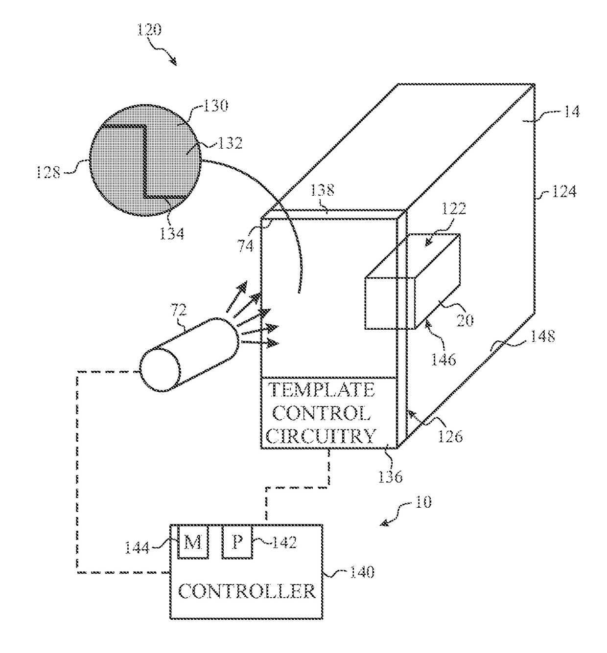
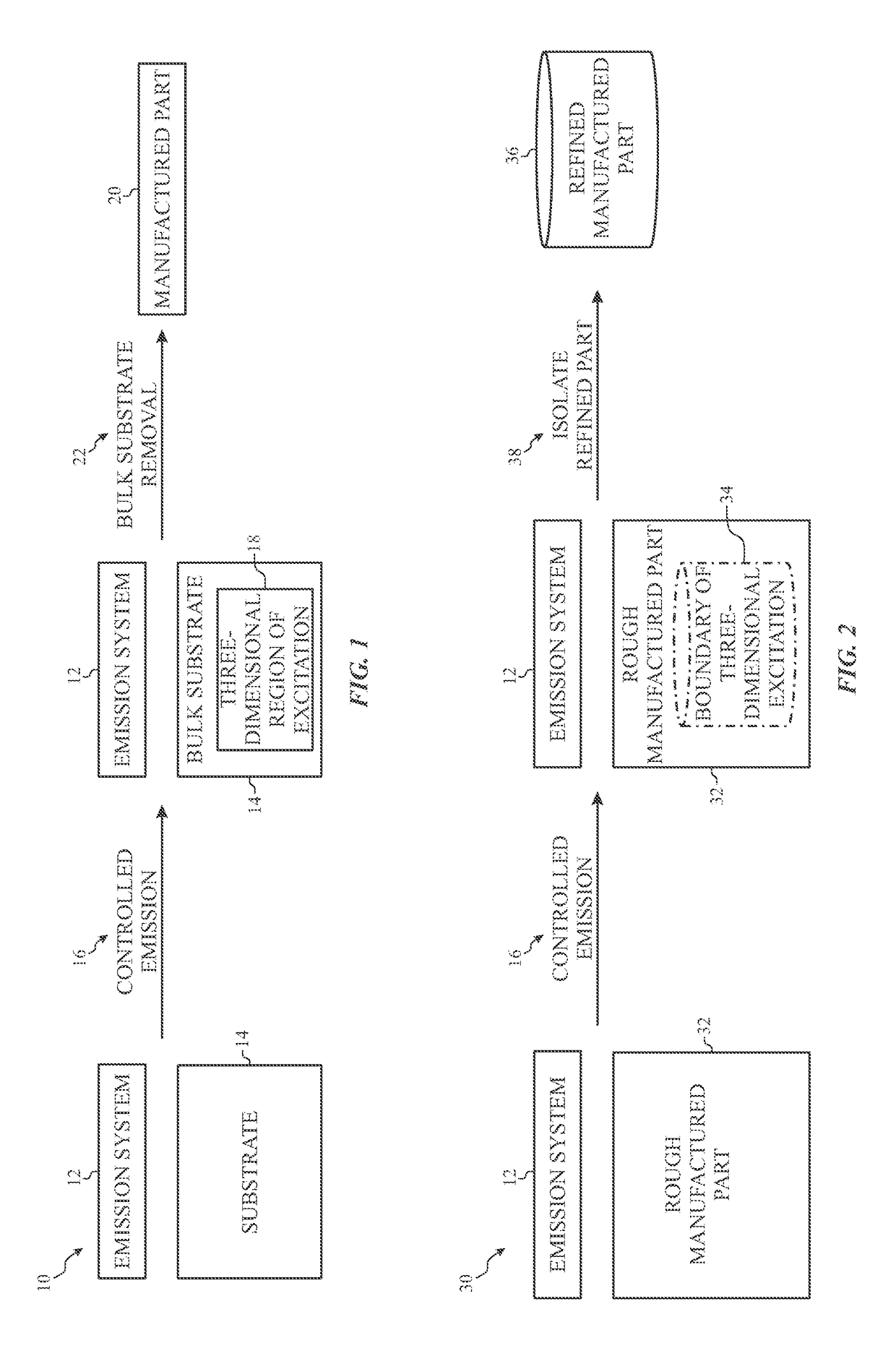
[0133] A method of manufacturing, comprising: selectively forming an article of manufacture using focused excitation by a process comprising: generating vibrations in a base material disposed within a build chamber; focusing the vibrations in a section of the base material; and controlling the focusing of the vibrations to cause the section of the base material to undergo a physical transformation to form at least a portion of the additive manufacturing part.

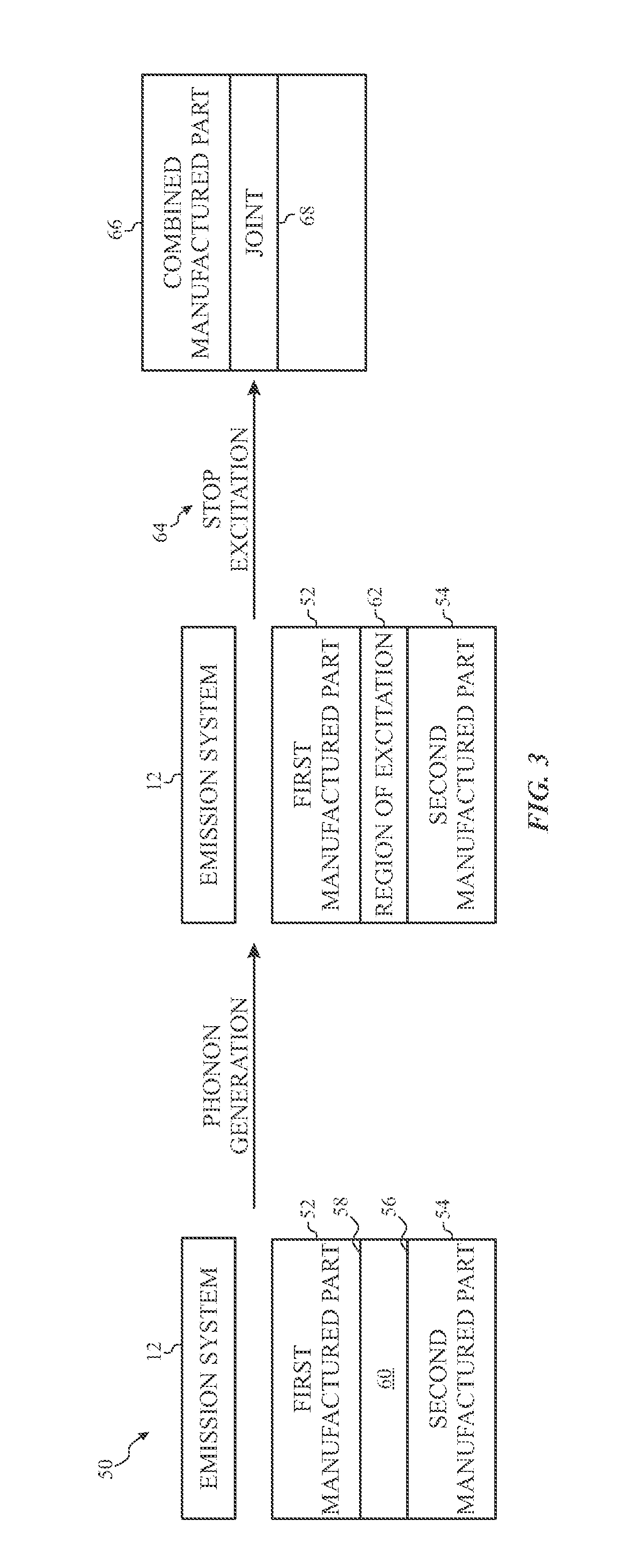
[0134]Embodiment 2. The method of embodiment 1, wherein generating vibrations in the base material comprises directing a waveform into the base material to cause phonon propagation through a lattice of the section of the base material, wherein the waveform includes infrasonic, sonic, or ultrasonic frequencies, or any combination thereof, or includes a thermal emission, or includes an emission generated from a phoxonic crystal.

embodiment 3

[0135] The method according to any preceding embodiment, wherein directing the waveform into the base material comprises directing a first waveform into a phononic or phoxonic crystal using an acoustic source, forming a second waveform from the first waveform in the phononic or phoxonic crystal, and directing the second waveform into the section of the base material.

embodiment 4

[0136] The method according to any preceding embodiment, wherein forming the second waveform from the first waveform in the phononic or phoxonic crystal comprises directing the first waveform into a focusing region of the phononic or phoxonic crystal having a matrix and inclusions positioned within the matrix, the inclusions having a spatial periodicity corresponding to a desired bandgap in the second waveform.


PUM

PropertyMeasurementUnit
Temperatureaaaaaaaaaa
Pressureaaaaaaaaaa
Frequencyaaaaaaaaaa

Abstract

Disclosed embodiments include the formation of an article of manufacture by a process in which vibrations are generated in a bulk material disposed within a build chamber. The vibrations are focused within a section of the base material, and the focusing is controlled to cause the section of the base material to undergo a physical transformation to form at least a portion of the article of manufacture.

Description

BACKGROUND[0001]The present techniques relate to the field of methods for producing articles of manufacture, such as additive manufacturing methods.[0002]This section is intended to introduce the reader to aspects of art that may be related to aspects of the present disclosure, which are described and / or claimed below. This discussion is believed to be helpful in providing the reader with background information to facilitate a better understanding of the various aspects of the present disclosure. Accordingly, it should be understood that these statements are to be read in this light, and not as admissions of prior art.[0003]Many of the products and goods that we use today, from simple to complex, are ultimately produced from basic materials such as polymers, ceramics, metals, and the like. Even certain advanced materials developed through cutting edge research include specific forms of these materials. Currently, there are a number of ways to use these different types of materials t...

Claims


Application Information

Patent Timeline
IPC IPC(8): B29C67/00B33Y30/00B29C64/291B29C64/35B29C64/153B29C64/129B33Y10/00B28B1/093B22F3/105B29C64/286B29C64/141C04B35/64B33Y50/02B28B1/00B22F3/00B22F3/093B29K23/00B29K25/00B29K55/00B29K83/00B29K105/00
CPCB29C67/0033B22F3/1055B28B1/093B29C64/129B29C64/141B29C64/153B29C64/286B29C64/291B29C64/35B33Y10/00B33Y30/00C04B35/64Y02P10/295C04B2235/667B22F3/008B22F3/093B22F2003/1056B22F2999/00B28B1/001B29K2023/06B29K2023/12B29K2025/06B29K2055/00B29K2065/00B29K2083/00B29K2105/251B29K2105/253B33Y50/02C04B2235/66B22F2202/01Y02P10/25B22F10/30B22F12/33B22F12/44B22F12/37B22F10/28B22F12/43B22F12/226B22F12/224
Inventor BROWN, JR., ALFRED E.
Owner CHEVRON PHILLIPS CHEMICAL CO LP
Learn More