Apparatus for attaching an insulated panel to a facade

a technology for attaching insulated panels and facades, which is applied in the direction of covering/linings, constructions, buildings, etc., to achieve the effect of durable and reliable operation and faster installation of panels

Active Publication Date: 2018-10-02
FAIRVIEW ARCHITECTURAL LLC
View PDF22 Cites 5 Cited by
  • Summary
  • Abstract
  • Description
  • Claims
  • Application Information

AI Technical Summary

Benefits of technology

[0025]Yet another object of the present application is to provide an apparatus for fabricating and mounting a plurality of panels to a façade that is durable and reliable in operation.
[0026]Anoth...

Problems solved by technology

The disadvantage of a progressive style panel system is that if a single panel must be ...

Method used


Image

  • Apparatus for attaching an insulated panel to a facade
  • Apparatus for attaching an insulated panel to a facade
  • Apparatus for attaching an insulated panel to a facade

Examples


Embodiment Construction

[0062]The apparatus as a whole is shown in the prior described drawings. Many aspects of the present apparatus, which are being sought for patenting, may evolve from the following detailed description of the preferred embodiments thereof which should be referenced to such prior described drawings.

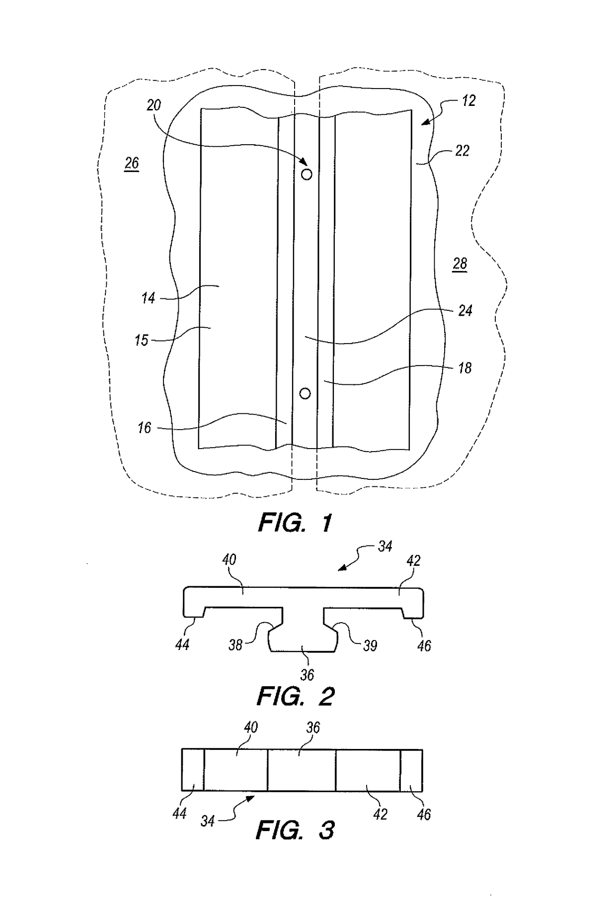
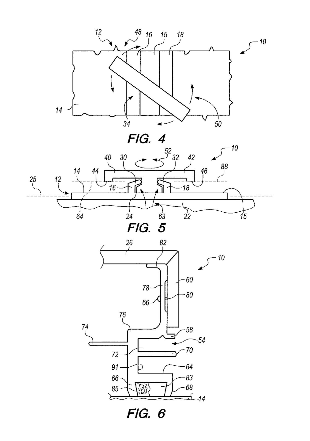
[0063]An apparatus for mounting a plurality of panels to a façade is depicted in the drawings by reference character 10, with variation noted by the addition of an uppercase letter. Apparatus 10 includes as one of its elements a base or field extrusion 12. Base 12 possesses a plate 14, having surface 15, and first and second flanges 16 and 18 that extend outwardly from plate 14, best shown in FIGS. 1 and 5. A fixing element 20, which may take the form of a plurality of rivets, screws, and the like, holds base 12 to façade 22 which may be the side of a building or edifice. Flanges 16 and 18 form a channel 24 therebetween. In the assembled state of apparatus 10, which will be discussed in det...


PUM


Abstract

An apparatus for attaching an insulated panel to a facade utilizing a bracket having a platform and an arm, each connected to the insulated panel in separate places. The bracket is locked to the facade and may be formed with thermal breaks between the insulated panel and the facade.

Description

CROSS-REFERENCES TO RELATED APPLICATIONS[0001]The present application is a Continuation-In-Part of U.S. patent application Ser. No. 15 / 048,842 filed 19 Feb. 2016.BACKGROUND OF THE INVENTION[0002]The present invention relates to a novel and useful system for mounting panels to a façade found on building structures and the like.[0003]Panels are often used on residential and commercial buildings to cover walls or facades since they have proved to be economical, protective of the edifice, and exhibit a high degree of design versatility, when compared to other coverings.[0004]In the past, panel systems have been employed that are categorized as “progressive style systems”. That is to say, that the panels are installed progressively from left to right on the bottom row of a building façade and then upwardly one row at a time in the same direction. The disadvantage of a progressive style panel system is that if a single panel must be removed, many other panels must also be removed prior to...

Claims


Application Information

Patent Timeline
IPC IPC(8): E04F13/08E04B1/41E04B1/38
CPCE04F13/0832E04B1/40E04F13/0875E04B2001/405E04F13/0826E04F13/0891E04F13/0898E04F13/12
Inventor SIMONSEN, DAVID
Owner FAIRVIEW ARCHITECTURAL LLC
Why Eureka
Try Eureka