Double-surface contact tray loading base

a technology of loading base and contact tray, which is applied in the direction of display hangers, cabinets, packaging, etc., can solve the problems of low strength and fatigue life of the hook, frequent stress concentration, and bad stress state of the hook, so as to improve the loading capacity and service life

Active Publication Date: 2018-10-09
CRRC MEISHAN
View PDF105 Cites 4 Cited by
  • Summary
  • Abstract
  • Description
  • Claims
  • Application Information

AI Technical Summary

Benefits of technology

[0003]The present invention aims to solve the problems mentioned above, and provides a tray support device having reasonable stress state and improved loading capability and service life. The technical solution is as follows:
[0010]1. The hook lug and the support plate are respectively arranged on the upper and lower sides of the outer end of the loading surface, thus forming the double-surface contact tray loading base. In a working position, the base is mounted in a seat form on a bracket which is mounted on the side wall of a compartment, with the mounting surface of the hook lug being pressed on a square hole of the bracket, the inner contact surface of the hook lug being in contact with the inner surface on the upper side of the bracket, the outer contact surface of the support plate being in contact with the outer surface on the lower side of the bracket, thus changing the single-sided stress state in the prior art. With the double-sided contact stress between the hook lug and support plate and the bracket, the stress area is increased, the stress delivered to the bracket is dispersed, and the stress delivered to the side wall and the bracket is reduced, as a result, the problem of stress concentration in the existing structures is avoided, the stability of the base is improved, the loading capacity of the base is increased by 80%, the service life is increased by about 68%, thus ensuring the safety of cargo transport.
[0011]2. The hook lug and the support plate limit the transversal movement of the base to prevent the base from falling from the bracket, thus ensuring the stability of the base.
[0012]3. The longitudinal stopper and the transversal stopper are arranged at the adjacent edges of the loading surface respectively, so as to limit the transversal and longitudinal movement of the base, thus ensuring the stability of the base during the cargo transport process.
[0014]5. The longitudinal stopper is tilted towards the direction of the hook with an angle of 2-30 degrees, so as to take the guide effect when the base is mounted.
[0015]6. The use of the reinforcement rib improves the strength of the base, increases the vertical loading capability of the base, and increases the fatigue life and service life.

Problems solved by technology

In this structure, the state of stress on the hooks is bad, the strength and fatigue life of the hooks are lower, the problem of stress concentration occurs frequently.
When in use, the device is prone to cracks, even tears, resulting in a severe impact on the safety of cargo transport.

Method used


Image

  • Double-surface contact tray loading base
  • Double-surface contact tray loading base
  • Double-surface contact tray loading base

Examples


embodiment 1

The Embodiment 1

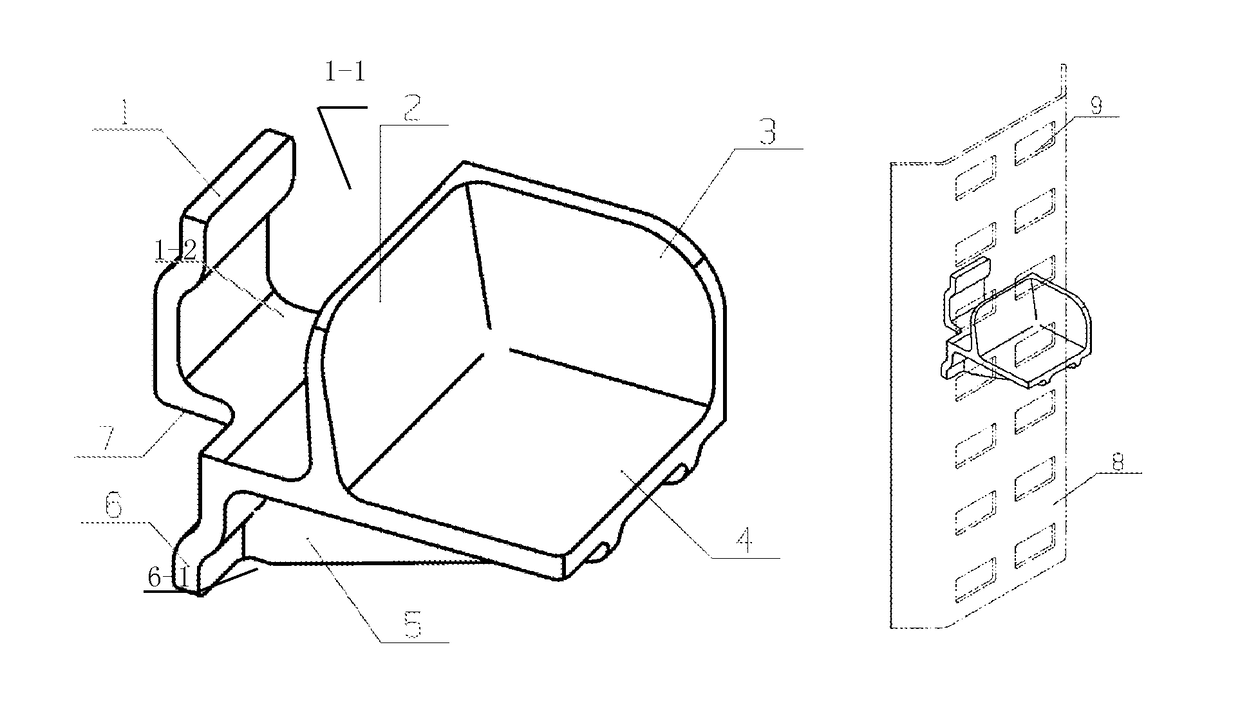
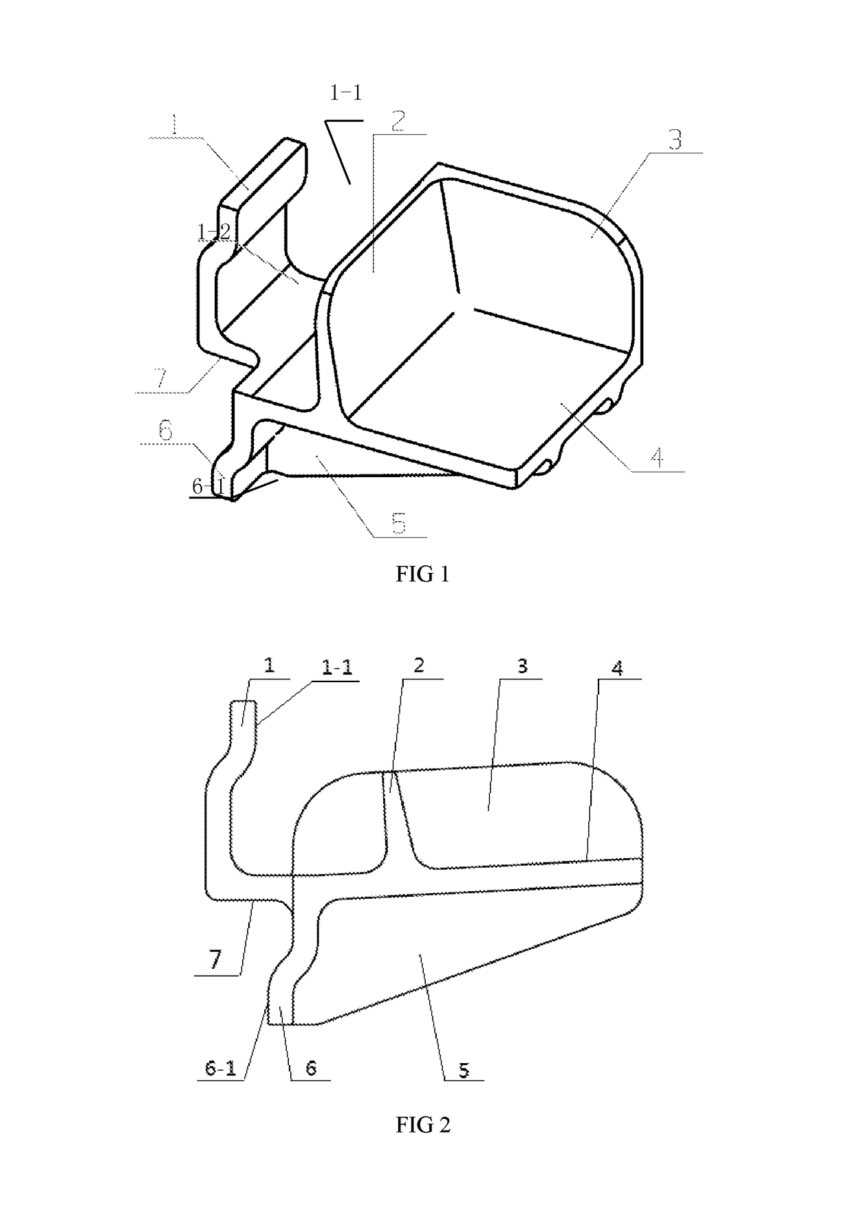
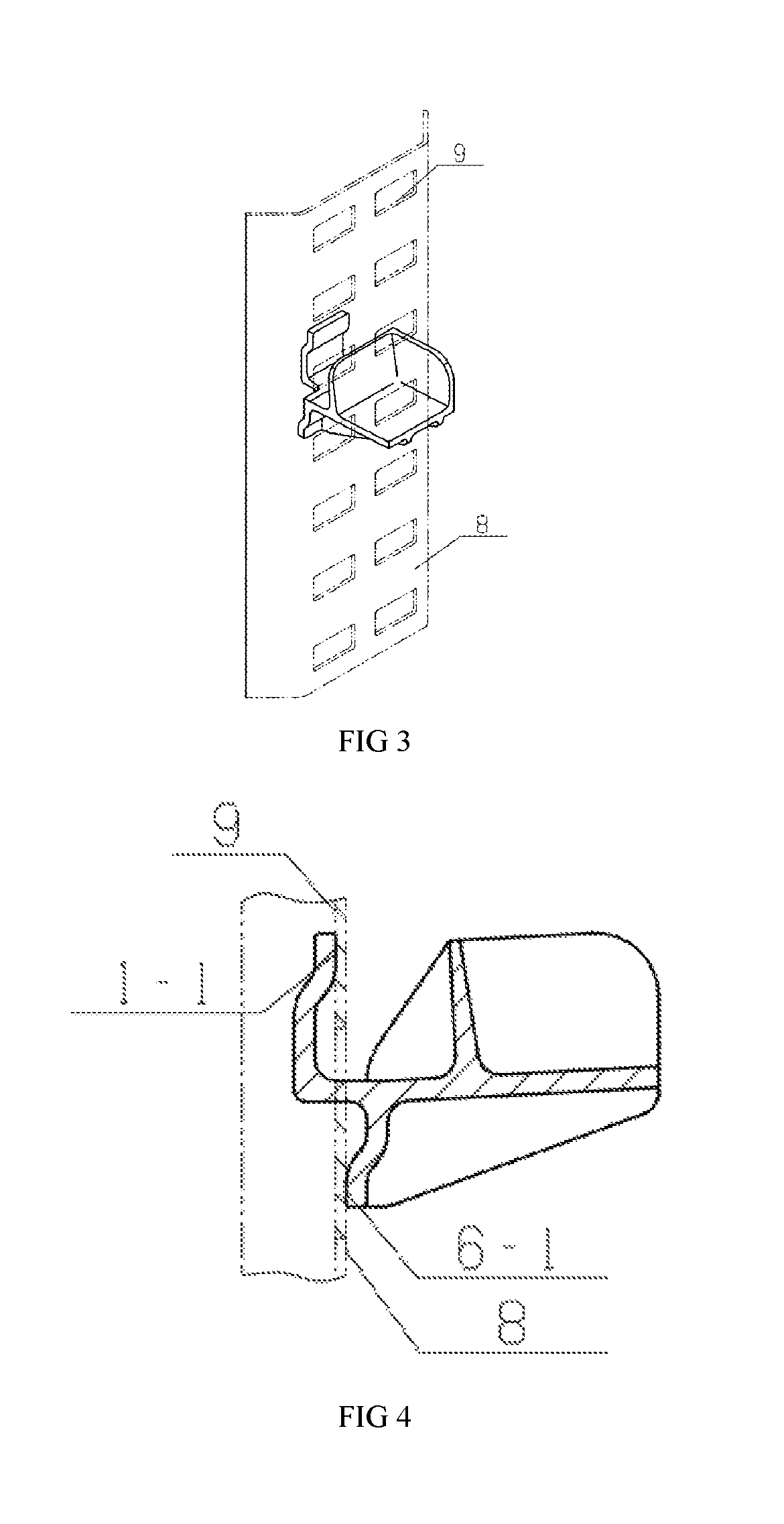
[0020]Referring to FIG. 1 and FIG. 2, the present embodiment comprises a loading surface 4 and a hook 1 arranged on the outer end of the loading surface 4, and is characterized in that the hook 1 comprises a hook lug 1-2 and a support plate 6, the hook lug 1-2 is arranged on an upper side of the outer end of the loading surface, the support plate 6 is arranged on a lower side of the outer end of the loading surface, thus forming the double-surface contact tray loading base. The hook lug 1-2 has a mounting surface 7 at the lower end, which is connected to an upper side of the outer end of the loading surface, and the hook lug has an inner contact surface 1-1 at the upper end. The support plate 6 has an outer contact surface 6-1 at the lower end.

embodiment 2

The Embodiment 2

[0021]The present embodiment comprises a loading surface 4 and a hook 1 arranged on an outer end of the loading surface 4, and is characterized in that the hook 1 comprises a hook lug 1-2 and a support plate 6, the hook lug 1-2 is arranged on an upper side of the outer end of the loading surface, the support plate 6 is arranged on a lower side of the outer end of the loading surface, thus forming the double-surface contact tray loading base. The hook lug 1-2 has a mounting surface 7 at the lower end, which is connected to the upper side of the outer end of the loading surface, and the hook lug has an inner contact surface 1-1 at the upper end. The support plate 6 has an outer contact surface 6-1 at the lower end. A longitudinal stopper 2 and a transversal stopper 3 are arranged at the adjacent edges of the loading surface 4, respectively.

embodiment 3

The Embodiment 3

[0022]The present embodiment comprises a loading surface 4 and a hook 1 arranged on an outer end of the loading surface 4, and is characterized in that the hook 1 comprises a hook lug 1-2 and a support plate 6, the hook lug 1-2 is arranged on an upper side of the outer end of the loading surface, the support plate 6 is arranged on a lower side of the outer end of the loading surface, thus forming the double-surface contact tray loading base. The hook lug 1-2 has a mounting surface 7 at the lower end, which is connected to the upper side of the outer end of the loading surface, and the hook lug has an inner contact surface 1-1 at the upper end. The support plate 6 has an outer contact surface 6-1 at the lower end. A longitudinal stopper 2 and a transversal stopper 3 are arranged at the adjacent edges of the loading surface 4, respectively. A reinforcement rib 5 is arranged at the bottom of the loading surface 4.


PUM


Abstract

A double-surface contact tray loading base comprises a loading surface (4) and a hook (1) arranged on an outer end of the loading surface (4), the hook (1) comprises a hook lug (1-2) and a support plate (6), the hook lug (1-2) is arranged on an upper side of the outer end of the loading surface (4), and the support plate (6) is arranged on a lower side of the outer end of the loading surface (4), thus forming the double-surface contact tray loading base.

Description

TECHNICAL FIELD[0001]A double-surface contact tray loading base relates to a cargo transport device, in particular to a tray for container transportation, belonging to the technical field of cargo transport.BACKGROUND ART[0002]At present, during the container transportation of cargo, trays are widely used in a compartment for the purpose of sorting and layering cargo, however, in terms of tray support, a simple method is adopted, which is implemented by hanging the hooks and loading surfaces on brackets which are mounted on the side walls of the compartment, so as to support the trays. In this structure, the state of stress on the hooks is bad, the strength and fatigue life of the hooks are lower, the problem of stress concentration occurs frequently. When in use, the device is prone to cracks, even tears, resulting in a severe impact on the safety of cargo transport.SUMMARY OF THE INVENTION[0003]The present invention aims to solve the problems mentioned above, and provides a tray s...

Claims


Application Information

Patent Timeline
Patent Type & Authority Patents(United States)
IPC IPC(8): A47F5/08B65D19/38B65G1/14A47B57/42A47B57/40
CPCB65D19/385B65G1/14A47B57/42A47B57/40B65D19/38B65D2519/00776A47B57/404A47B96/024A47B96/068A47B96/1408A47B2220/0041A47B57/06A47F5/08A47F5/00
Inventor HAN, JINGANGZHENG, PINGYANG, SHIWEIWANG, YIWANG, AIMINLI, DONGLI, JIANCHAOPENG, LIAOWANG, PU
Owner CRRC MEISHAN
Why Eureka
Try Eureka