Tray type retaining wall structure for weakening mutual influence of subgrade

A technology of mutual influence and retaining wall, which is applied in the direction of basic structure engineering, underwater structures, roads, etc., can solve the problems of affecting the service life of equipment, anti-frost heave performance, and poor durability, so as to achieve simple force, anti-corrosion Good frost heaving performance and high overall bearing capacity

Active Publication Date: 2016-09-07
辽宁建岳工程技术有限公司
View PDF8 Cites 1 Cited by
  • Summary
  • Abstract
  • Description
  • Claims
  • Application Information

AI Technical Summary

Problems solved by technology

However, due to the large amount of air bubbles contained in the light roadbed material, its frost heave resistance and durability are poor
Seriously affect the service life of the equipment

Method used


Image

  • Tray type retaining wall structure for weakening mutual influence of subgrade
  • Tray type retaining wall structure for weakening mutual influence of subgrade

Examples


Embodiment 1

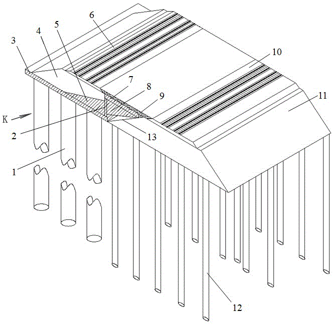
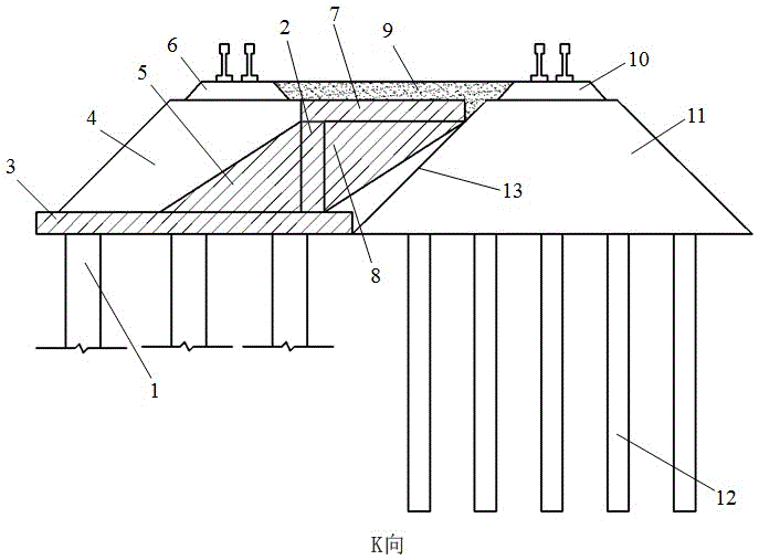
[0024] Such as figure 1 , 2 The shown pallet-type retaining wall structure for weakening the mutual influence between subgrades includes the existing subgrade bed 10, the existing subgrade body 11, the existing subgrade foundation 12 and the existing subgrade slope 13, which along the existing subgrade The bottom surface of one side of the slope 13 in the length direction is provided with a base plate 3, and along the length direction of the lower end of the base plate 3, several row pile foundations 1 are arranged at even intervals, and a retaining wall 2 is arranged at the matching position of the upper end of the base plate 3. The soil wall 2 is composed of a longitudinal baffle and a horizontal baffle 7 vertically overlapped and fixedly connected at one end, the other end of the horizontal baffle 7 is overlapped with the existing roadbed slope 13, and the side of the vertical baffle far away from the horizontal baffle 7 is provided with a newly built The road basic body 4...

Embodiment 2

[0030] Such as figure 1 , 2 The shown pallet-type retaining wall structure for weakening the mutual influence between subgrades includes the existing subgrade bed 10, the existing subgrade body 11, the existing subgrade foundation 12 and the existing subgrade slope 13, which along the existing subgrade The bottom surface of one side of the slope 13 in the length direction is provided with a base plate 3, and along the length direction of the lower end of the base plate 3, several row pile foundations 1 are arranged at even intervals, and a retaining wall 2 is arranged at the matching position of the upper end of the base plate 3. The soil wall 2 is composed of a longitudinal baffle and a horizontal baffle 7 vertically overlapped and fixedly connected at one end, the other end of the horizontal baffle 7 is overlapped with the existing roadbed slope 13, and the side of the vertical baffle far away from the horizontal baffle 7 is provided with a newly built The road basic body 4...


PUM


Abstract

The invention discloses a tray type retaining wall structure for weakening mutual influence of subgrade. The tray type retaining wall comprises a subgrade ballast bed, an existing subgrade body, an existing bottom foundation of subgrade and an existing subgrade slope, wherein a bottom plate is arranged on the bottom surface in the length direction of one side of the existing subgrade slope and a plurality of pile foundations are evenly arranged in the length direction of the lower end of the bottom plate at intervals. The retaining wall is formed by the vertical overlapping and fixed connection between a longitudinal baffle and one end of a horizontal baffle, and the other end of the horizontal baffle and the existing subgrade slope are overlapped. One side, away from the horizontal baffle, of the longitudinal baffle is provided with a newly-built subgrade body, the upper end of the horizontal baffle is provided with a leveling layer between lines, and the left and right sides of the leveling layer between lines are respectively consistent with the newly-built subgrade ballast bed and the existing subgrade ballast bed at the upper ends of the newly-built subgrade body and the existing subgrade body. The tray type retaining wall structure for weakening the mutual influence of the subgrade is high in bearing capacity, higher in earth retaining, broad in application range, convenient to construct, long in service life and better in economic and social benefit.

Description

technical field [0001] The invention relates to a retaining wall structure, in particular to a tray-type retaining wall structure for weakening mutual influence between roadbeds. Background technique [0002] With the rapid development of highway and railway construction, there are also more engineering projects for rebuilding and expanding various existing roads and adding new railway lines beside existing railway lines. The construction and construction process of these engineering projects will have a certain impact on the existing roads and railways. In addition, the self-weight and vehicle loads borne by newly-built roads and railways will also be transmitted and diffused through their own foundations to the depths of the foundation, causing additional stress and deformation on the subgrade base of existing lines, resulting in additional post-construction settlements, which will affect The performance of existing roads and railway subgrades. Common engineering measure...

Claims


Application Information

Patent Timeline
Patent Type & Authority Applications(China)
IPC IPC(8): E01C3/00E02D27/12E02D29/02
CPCE01C3/00E02D27/12E02D29/02
Inventor 郭超陆征然李微高原
Owner 辽宁建岳工程技术有限公司
Why Eureka
Try Eureka