Male or female quick coupling element and quick coupling including such an element

a technology of quick coupling and element, which is applied in the direction of couplings, pipe joints, mechanical devices, etc., can solve the problems of not being compatible with all coupler sizes, affecting the maneuverability of the coupler, and affecting the stability of the coupler, so as to reduce the residual pressure, the effect of good compactness of the opening mechanism and simple, reliable and cost-effective approach

Active Publication Date: 2018-10-09
STAUBLI FAVERGES SA
View PDF12 Cites 5 Cited by
  • Summary
  • Abstract
  • Description
  • Claims
  • Application Information

AI Technical Summary

Benefits of technology

[0011]Owing to the invention, the activation of the mechanism for opening the fluid channel makes it possible to allow a sufficient quantity of pressurized fluid to escape to lower the residual pressure in the inner volume of the coupling element, to the point that the pressure exerted on its flap can easily be overcome by the operator when nesting the male and female elements in one another. The presence of the seal in the groove of the inner part makes it possible to produce an annular sealing section within the drain passage. The control member makes it possible to create a leak at this seal, when it acts on the seal, in particular to unstick this seal relative to the bottom of the groove against which the seal rests by default, i.e., when it is in its closing off position. Using a peripheral groove and a seal makes it possible to obtain good compactness of the opening mechanism of the drain passage and to use a simple, reliable and cost-effective approach. It requires few structural modifications relative to a traditional coupler. The invention applies indifferently to a male or female coupling element.

Problems solved by technology

These flaps are subject to the internal pressure of each coupling element, this pressure being able to be high and led to increase in its environment, to the point of hindering the maneuvering of the coupler, inasmuch as the operator may experience difficulties in overcoming the resisting force exerted by the pressure of the fluid inside the coupling elements, against the flaps.
Such as non-return flap is relatively bulky, which is not compatible with all coupler sizes.
In particular, in some couplers with a small diameter, only a reduced space is available in the central part of each male or female element, which does not make it possible to accommodate the known mechanism.
Furthermore, the larger the diameter of the coupler is, the more the flaps may have extensive surfaces subject to the internal pressure of the coupler and the higher the resisting forces are with respect to the nesting.

Method used


Image

  • Male or female quick coupling element and quick coupling including such an element
  • Male or female quick coupling element and quick coupling including such an element
  • Male or female quick coupling element and quick coupling including such an element

Examples


second embodiment

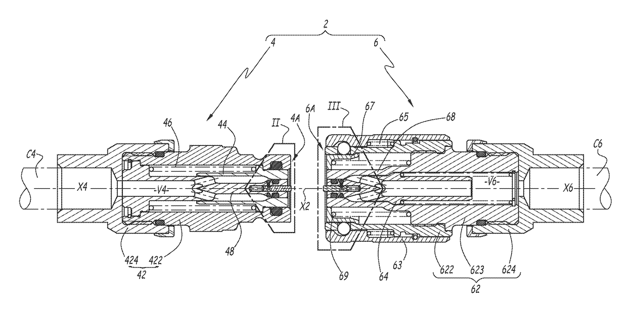
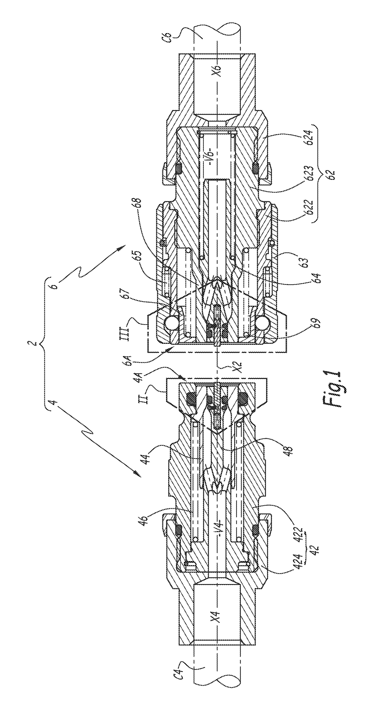
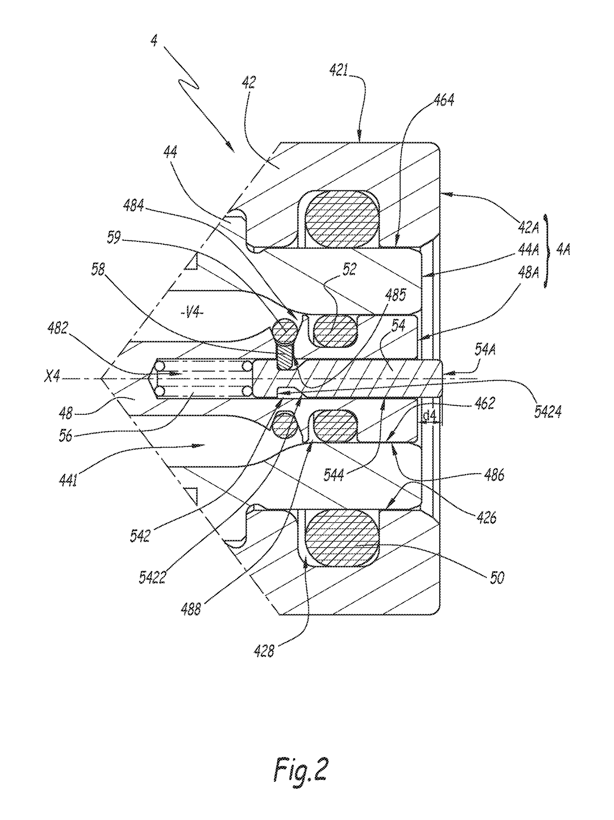
[0084]In the second embodiment shown in FIG. 9, only the male coupling element 4 is equipped with a mechanism for opening a drain passage, which comprises a piston 54, a spring 56, a pin 58 and a seal 59. The female element 6 of the coupler is a traditional element equipped with a central flap whereof the front face is aligned with the front face of the female element in the uncoupled position of the coupler, and able to push the piston 54 of the male element 4 back during the coupling phase.

[0085]The coupler 2 of this embodiment is adapted to the case with female element 6 of the coupler is connected to a pressurized fluid source, while the male element 4 is coupled to the inner pipes of an apparatus whereof the internal pressure can be made to increase in the uncoupled position of the elements, and the flap 44 contains an internal pressure great enough to hinder the coupling maneuver. The fluid flows from right to left in FIG. 9.

[0086]The invention is compatible with different pis...

first embodiment

[0087]According to one alternative of the invention that is not shown, a reverse configuration is implemented. In other words, the female element 6 is equipped with a mechanism for opening a drain passage formed by a piston, a spring, a pin and a seal, as explained above for the first embodiment, while the male element does not have these. This alternative is adapted to the case where only the male coupling element is supplied with pressurized fluid during the coupling of these elements.

third embodiment

[0088]In the third embodiment shown in FIG. 10, a cage 53 is attached on the plunger 48 to prevent the seal 59 from leaving the groove 484 when it is pushed back by the pin 58. In the example, this cage 53 is screwed on the plunger 48. Alternatively, it can be mounted on this plunger by other means, in particular by gluing or snapping.

[0089]The cage 53 is provided with several apertures 532 distributed around the axis X4, one of which is visible in the top part of FIG. 10, and which allow fluid to pass toward the groove 484. These apertures are therefore part of the drain passage. Between the apertures 532, and as shown in the bottom part of FIG. 10, a web 534 of the ring 53 closes off the groove 484, which keeps the seal 59 inside the groove 484.

[0090]Alternatively, other means for retaining the seal 59 in the groove 484 can be provided, such as elements forming a single piece with the plunger 48.

[0091]In the embodiment of FIGS. 11 and 12, a slotted ring 55 is inserted between the ...


PUM


Abstract

This male or female quick coupling element (4; 6) is intended to be coupled to a pressurized fluid pipe (C4; C6). It comprises a body (42; 62) defining at least one pressurized fluid passage (441, 643, 681), a front face and a longitudinal axis (X4; X6) of the coupling element. An inner part (48; 64) arranged in the body is provided with a surface belonging to the front face, as well as a drain passage (482, 484; 642, 644) coupling the pressurized fluid passage and the outside of the coupling element. An opening mechanism (54, 56, 58, 59; 74, 76, 78, 78) is intended to be actuated from the front face of the coupling element to open the drain passage. The inner part (48; 64) is provided with a peripheral groove (484; 644) in which a seal (59; 79) rests that closes off the drain passage (482, 484; 642, 644) in a closing off portion. The opening mechanism is mounted in the inner part and comprises at least one member (58; 78) for controlling the position of the seal (59; 79) relative to the groove (484; 644), this control member being movable between a first inactive position, where it does not move the seal relative to its closing off position, and a second active position, where it acts directly on the seal (59; 79) to open the drain passage (482, 484; 642, 644).

Description

BACKGROUND OF THE INVENTION[0001]The invention relates to a male or female quick coupling element, as well as a quick coupling including such an element.[0002]The invention more particularly relates to the quick couplers used to couple pressurized fluid pipes. With a quick coupler, when coupling two pressurized fluid pipes, a male element and a female element are nested in one another to create a pressurized fluid circulation tunnel. This coupling requires pushing back valve flaps which, in this case, belong to each of the male and female elements of the coupler. These flaps are subject to the internal pressure of each coupling element, this pressure being able to be high and led to increase in its environment, to the point of hindering the maneuvering of the coupler, inasmuch as the operator may experience difficulties in overcoming the resisting force exerted by the pressure of the fluid inside the coupling elements, against the flaps. For example, for a coupler whereof the flap h...

Claims


Application Information

Patent Timeline
Patent Type & Authority Patents(United States)
IPC IPC(8): F16L37/34F16L37/23F16L37/32F16L37/35
CPCF16L37/32F16L37/35F16L37/34F16L37/23F16L37/38F16L37/62F16L29/04F16L37/36
Inventor TIBERGHIEN, ALAIN-CHRISTOPHEDURIEUX, CHRISTOPHEMAYER, ROMAIN
Owner STAUBLI FAVERGES SA
Why Eureka
Try Eureka