Shield connector

a shield connector and connector technology, applied in the direction of coupling/case, coupling device connection, electrical equipment, etc., can solve the problems of the shield being broken and the cover being detached from the outer housing, and achieve the effect of suppressing the detachment of the cover and protecting more reliably

Active Publication Date: 2018-10-16
AUTONETWORKS TECH LTD +2
View PDF23 Cites 9 Cited by
  • Summary
  • Abstract
  • Description
  • Claims
  • Application Information

AI Technical Summary

Benefits of technology

[0008]The first locking means may be provided on a tubular portion of the covers configured to cover the connecting portion. According to this configuration, the tubular portion is more difficult to open, and therefore the connecting portion can be protected more reliably protected.
[0009]According to this specification, a shield connector is obtained that suppresses the detachment of a cover even if a hinge is broken.

Problems solved by technology

However, in this configuration, the hinge may be broken and the cover may be detached from the outer housing, such as when the cover is repeatedly opened and closed for maintenance and the like.

Method used


Image

  • Shield connector
  • Shield connector
  • Shield connector

Examples


Embodiment Construction

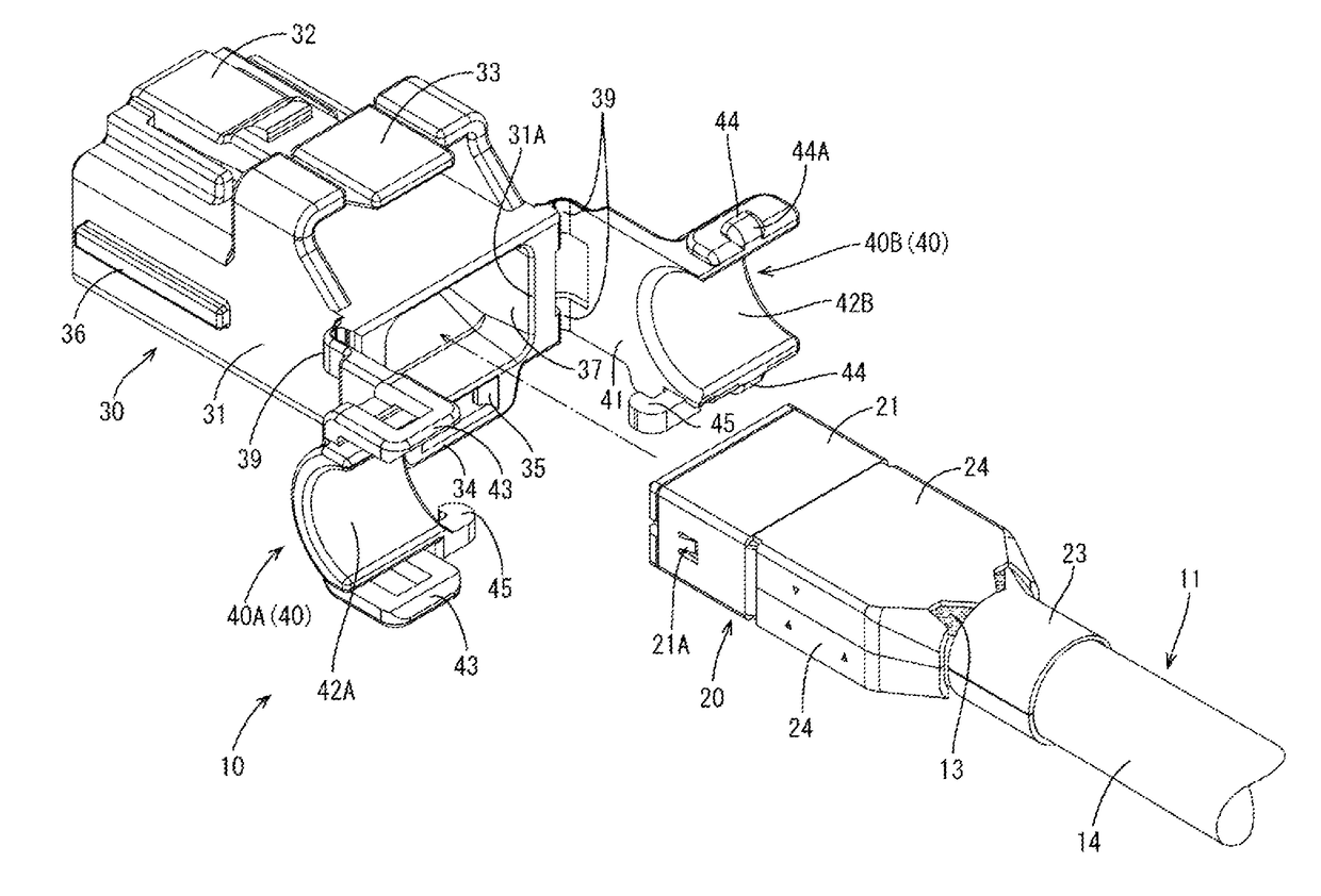
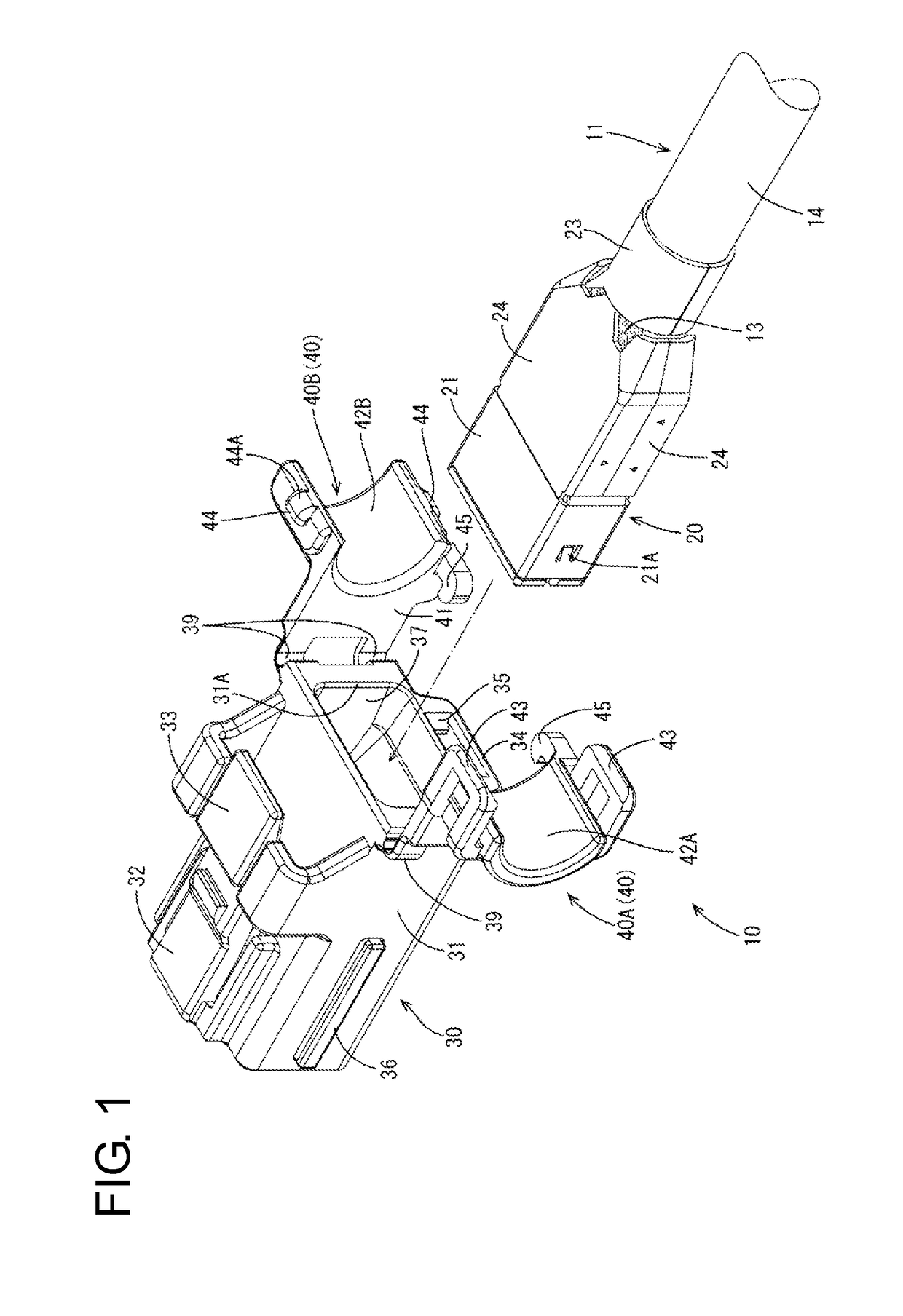
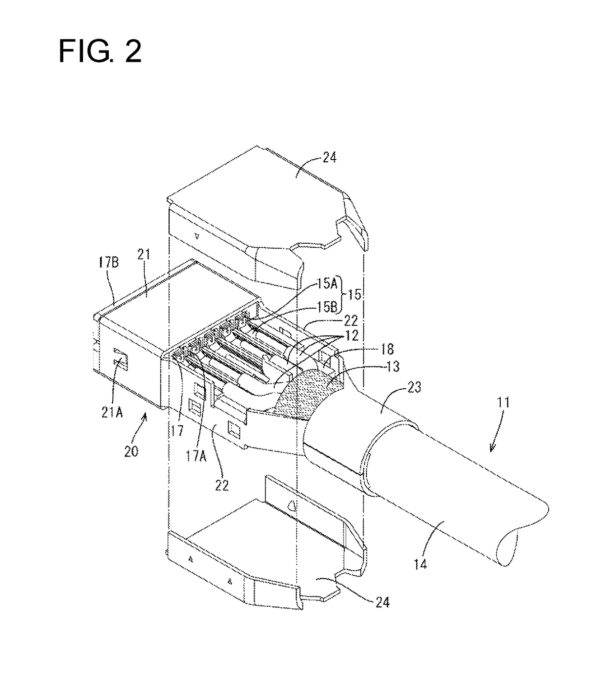
[0022]One embodiment is described with reference to FIGS. 1 to 12. A shield connector 10 is mounted in a vehicle such as an automotive vehicle and arranged in a wired communication path between an in-vehicle electrical component (car navigation system, ETC, monitor or the like) and an external device (camera or the like) or between in-vehicle electrical components in a vehicle. In the following description, an upper side and a lower side of FIG. 1 are referred to as an upper side and a lower side concerning a vertical direction, a left-lower side and a right-upper side of FIG. 1 are referred to as a left side and a right side concerning a lateral direction, and a left-upper side and a right-lower side of FIG. 1 are referred to as a front side and a rear side concerning a front-rear direction. Further, for a plurality of identical members, one member may be denoted by a reference sign and the other members may not be denoted.

[0023]The shield connector 10 of this embodiment includes a...


PUM


Abstract

A shield connector includes a shielded cable (11) with wires (12) enclosed by a shield layer (13). An inner housing (16) accommodates terminals (15) connected to the wires (12). A shield shell (20) covers the inner housing (16) and includes a connecting portion (23) to be connected electrically to the shield layer (13). An outer housing (30) accommodates the shield shell (20) and is locked to a mating connector. The outer housing (30) includes a body (31) enabling the shield shell (20) to be inserted therein through an opening (31A) on a rear side, and two covers (40A, 40B) integrally hinged to the body (31) to close the opening (31A) and cover the connecting portion (23). Each cover (40A, 40B) includes a first lock (43, 44) to be locked to the mating cover and a second lock (45) to be locked to the body.

Description

BACKGROUND1. Field of the Invention[0001]The invention relates to a shield connector.2. Description of the Related Art[0002]Japanese Unexamined Patent Publication No. 2012-195315 is an example of a known shield connector for communication, and typically is mounted in a vehicle, such as an automotive vehicle. The connector is arranged in a wired communication path between an in-vehicle electrical component (car navigation system, ETC, monitor or the like) and an external device (camera or the like) or between in-vehicle electrical components in a vehicle. Such a shield connector includes an inner housing with cavities, and connection terminals are accommodated in the cavities for connecting mating terminals and signal wires. The inner housing is shielded collectively by a shield shell and the shield shell is connected electrically to a shield conductor of a shielded cable.[0003]Further, it is proposed to provide an outer housing outside the shield shell and reliably connect the conne...

Claims


Application Information

Patent Timeline
Patent Type & Authority Patents(United States)
IPC IPC(8): H01R9/03H01R13/648H01R13/658H01R13/52H01R13/516
CPCH01R13/648H01R9/032H01R13/516H01R13/5205H01R13/65802H01R13/5202H01R13/5208H01R13/501H01R13/506H01R13/658H01R13/65912
Inventor MAESOBA, HIROYOSHIICHIO, TOSHIFUMI
Owner AUTONETWORKS TECH LTD
Why Eureka
Try Eureka